

Geomechanical modelling of hydrogen storage at the CO2CRC Otway International Test Centre
R. Puspitasari A * , H. W. Moh A , E. Tenthorey B , Z. J. Pallikathekathil A , R. Dandekar A , M. A. Giddins C , O. Suriyanto D and A. J. Feitz BA
B
C
D

Ratih Puspitasari is a Senior Geomechanics Engineer at SLB in Australia. She holds a Master of Petroleum Engineering from Curtin University. With over 20 years of experience in the oil and gas industry, Ratih has worked in various areas, including cementing, stimulation, reservoir, and production. For the past 15 years, she has specialised in geomechanics, applying her expertise to a wide variety of applications such as drilling optimisation, methane hydrate modelling, and sanding analysis. Her current interests include 3D geomechanical modelling, carbon capture, and unconventional reservoirs. |

Hsiao Wun Moh graduated with a Bachelor’s Degree in Engineering from Universiti Teknologi Malaysia in 2001 and subsequently joined SLB. With more than 20 years in the energy industry, he has worked in Canada, Malaysia, and is presently based in Australia. He began his career as a Wireline Field Engineer and has since transitioned to his current role as Senior Reservoir Engineer. His expertise includes formation testing, downhole fluid sampling, production logging interpretation, and reservoir simulation. He is experienced in field development planning for conventional reservoirs and, more recently, in carbon capture and storage (CCS) over the past few years. |

Eric Tenthorey is a Senior Researcher at Geoscience Australia, with expertise in geomechanics, carbon capture, and other low carbon geoscience disciplines. He holds a PhD from Columbia University and subsequently worked as a researcher at the Australian National University. In 2007, he was engaged by Geoscience Australia to work as a geomechanics expert, focused on developing and proving up CCS technology. More recently, his work has centred on other low carbon geoscience sectors, such as the hydrogen energy future, geothermal energy, and CO2 storage in residual oil zones. |

Zachariah John Pallikathekathil graduated from the Indian Institute of Technology Delhi in Mechanical Engineering. He has held technical and management positions in wireline and logging-while-drilling log acquisition and interpretation. His passion for geomechanics and its multi-disciplinary requirement drew him into the field of geomechanics 15 years ago. He is currently involved in rock testing design, construction of 1D and 3D mechanical earth models for addressing issues on wellbore stability (drilling), completion integrity (sanding, casing), compaction–subsidence, and fault stability over the life of the field for oil and gas reservoirs and CCS projects. He is a member of SPE and was the past President of the SPWLA chapter in Australia in 2010 and 2011. |

Rashmin Dandekar is a Reservoir Engineer at SLB with over 32 years of experience in the upstream oil and gas industry. He holds a Master’s Degree in Petroleum Engineering from Texas A&M University. Throughout his career, Rashmin has specialised in several key areas of reservoir engineering, including reservoir management, reservoir characterisation and modelling, dynamic simulation, field development planning, uncertainty and risk analysis, reserves estimation, and classical reservoir engineering. Currently, he is focused on various aspects of subsurface storage of CO2 and hydrogen, including fluid modelling, thermal modelling, and related areas. |

Marie Ann Giddins is an Advisor in Reservoir Engineering, based in SLB’s Abingdon Technology Center in the UK. She has a BA in Mathematics from the University of Oxford and MSc in Operational Research from the University of Sussex, plus over 30 years of experience in the energy industry. Marie Ann provides technical advice to SLB and clients on reservoir simulation software, workflows, and integrated studies. Her areas of expertise include advanced reservoir engineering applications such as enhanced oil recovery (chemical enhanced oil recovery, miscible injection, and thermal studies), unconventional reservoirs, and non-Darcy flow in gas condensate fields. Her current focus is on new energy, including subsurface studies of CO2, hydrogen, geothermal reservoirs, and critical minerals. She is a mentor and coach for trainees and experienced engineers at all stages of professional development and has supervised over 80 student intern projects. |

Olivia Suriyanto is a Reservoir Engineer with experience in formation testing, downhole fluid analysis, production logging, reservoir simulation, wellbore stability analysis, and wireline logging operations. She holds a Master of Petroleum Engineering from Curtin University (Australia), and a Bachelor of Chemical Engineering from Gadjah Mada University (Indonesia). Olivia was previously a Senior Reservoir Engineer with SLB’s asset consulting team, focusing on reservoir simulation for oil and gas application, CCS, and underground gas storage. Her current interests are still related to new energy and energy transition, combined with an ongoing data science course, and with a dash of crafting and writing. |

Andrew Feitz is an Environmental Engineer and Director of Low Carbon Geoscience and Advice at Geoscience Australia. He holds a PhD from UNSW and worked as a senior researcher in air and water treatment technologies at UNSW and the Karlsruhe Institute of Technology (Germany). He moved to Canberra in 2008 and joined Geoscience Australia where he developed and led a research program to evaluate monitoring techniques for geological storage of carbon dioxide. Andrew leads Geoscience Australia’s efforts supporting establishment of a hydrogen industry in Australia and was a member of the Advisory Group for the 2024 National Hydrogen Strategy. |
Abstract
As part of the former ‘Exploring for the Future’ program (2016–2024), the Australian Government committed significant resources to lay the foundations for the nation’s future hydrogen economy. One component was to understand how to identify, characterise, and operate potential hydrogen storage sites. This paper presents a case study of hydrogen storage in a depleted gas field, focusing on geomechanical behaviour, using data from the CO2CRC Otway International Test Centre in Australia. This study is the first to compare fluid dynamic behaviour and geomechanical risks of hydrogen storage with the more extensively studied methane and carbon dioxide (CO2) storage. At reservoir depth, hydrogen exhibits large differences in density, compressibility, viscosity, and thermal properties compared to the other gases, necessitating different operational approaches for underground storage. The study’s uniqueness lies in the inclusion of coupled reservoir geomechanics with thermal simulation in reservoir and cap rock, using a high-resolution grid around the wellbore. A key finding is that hydrogen storage causes significantly less thermal perturbation compared to methane and CO2 storage under an identical reservoir injection volume. The fault reactivation and wellbore fracturing risk due to thermally-induced stress changes are lower in hydrogen storage compared to CO2 storage. Simulations suggest that reducing the injection rate dampens both temperature and pressure effects, further reducing the risk of wellbore fracturing and fault reactivation. This study highlights the potential advantages of integrating reservoir flow simulation with geomechanical risk assessment. Implementing dynamic control mechanisms in coupled simulations could optimise injection rates without compromising underground storage safety.
Keywords: CO2 storage, depleted gas field, fault stability, gas storage, geomechanics, hydrogen storage, reservoir simulation, thermal modelling, wellbore fracturing.
Introduction
The Australian Government is interested in identifying locations with high potential for underground hydrogen storage (DCCEEW 2024), to support a net zero energy future by 2050. In this study, we model and explore the technical issues around hydrogen (H2) storage in depleted gas fields, focusing on injection, flow, and geomechanical response.
Depleted hydrocarbon fields have proven to be excellent sites for natural gas storage, as they have seals that have trapped hydrocarbons for millions of years, and the pressure response of the system is well characterised and modelled in most cases. The assumption is therefore that these fields may be used to store another gas safely after production. In the case of H2, differences in physical properties and chemical behaviour compared to natural gas require some research before implementing hydrogen storage in depleted fields.
In this paper, we investigate the geomechanical effects of hydrogen injection and withdrawal operations from a case study completed as part of the former Australian Government’s ‘Exploring for the Future’ program (2016–2024). We present the results from 3D coupled simulation models using an early model of a depleted gas reservoir from the Otway International Test Centre (OITC) as a template, as the site has been well characterised and history matched. Tenthorey et al. (2024) compared H2 injection with injection of methane (CH4) and carbon dioxide (CO2), considering the fluid flow dynamic behaviour and the different thermal effects under the tested conditions. This paper expands further upon the thermal perturbations caused by the injection of H2 and discusses how injection rate can have a significant impact on geomechanical integrity. Additionally, we compare thermal and non-thermal models to understand the implications of excluding thermal cooling on the stress state and geomechanical risk. We also discuss the importance of model construction including embedding the reservoir simulation grid into the geomechanical grid and use of local grid refinements to produce accurate model results.
The Otway International Test Centre
The OITC has been used for approximately 20 years to conduct a variety of CO2 injection experiments within various geological formations, down to approximately 2200 m depth. Research at the site was initiated in 2003 and it has hosted several important CO2 injection tests that are well documented (e.g. Jenkins et al. 2012; Haese et al. 2013; Tenthorey et al. 2014; Pevzner et al. 2017; Feitz et al. 2022; Jackson et al. 2024).
The focus of the modelling presented in this paper is on the Waarre C Formation, a prolific gas reservoir interval in the Otway Basin. At the OITC, the Waarre C Formation forms the gas reservoir in a faulted anticlinal structural trap, which defines the Naylor Field (a depleted natural gas field). The field, with an initial gas-in-place of 4.86 Bcf, produced gas from June 2002 to October 2003 achieving a recovery factor of 71%. The field’s initial pressure was 192 bar, which depleted to a minimum of 142 bar but rebounded to 179 bar after production ceased due to an active aquifer. During the first stage of operations at the OITC, the field was used for the injection of 66,000 tonnes of CO2 into the Waarre C Formation (Jenkins et al. 2012). The Naylor Field reservoir is approximately 2200 m below the surface. It is bounded to the north and west by the Naylor Fault and to the east by the Eastern Bounding Fault. These faults provided a structural trapping mechanism for the initial natural gas column through providing a juxtaposing seal with the overlying Belfast Mudstone. The Naylor Field is a good analogue for a gas field being transformed into a hydrogen storage facility.
Modelling approach
We use numerical simulations of coupled fluid flow and geomechanics to model the hydromechanical behaviour of H2, CO2, and natural gas storage. Numerical simulations, unlike analytical methods, can account for material non-linearities, complex geometries, and varying load conditions, and provide accurate results for complex problems, such as those modelled here. We employ a one-way sequential coupling scheme, where the fluid flow simulator provides pressure and temperature results at predefined coupled time-steps to the geomechanics simulator, which computes the resulting stresses and strains in the system. This approach is typically sufficient when the primary focus is on the geomechanical response to fluid-induced changes in pressure or temperature and has the benefit of minimising computational complexity and runtime.
Thermal modelling is included because injecting cold fluid into a hot reservoir can create a cooling effect significant enough to cause large rock contraction. This contraction reduces stresses, making the rock more susceptible to failure in both tensile and shear modes. The thermal effect is most pronounced in the injected zone of the reservoir, where convective heat flow dominates. The cooling effect in the reservoir is then transferred to the cap rock through conductive heat flow. Although the thermal effect in the cap rock is smaller than in the reservoir, it should be accounted for to improve the accuracy of modelling cap rock integrity.
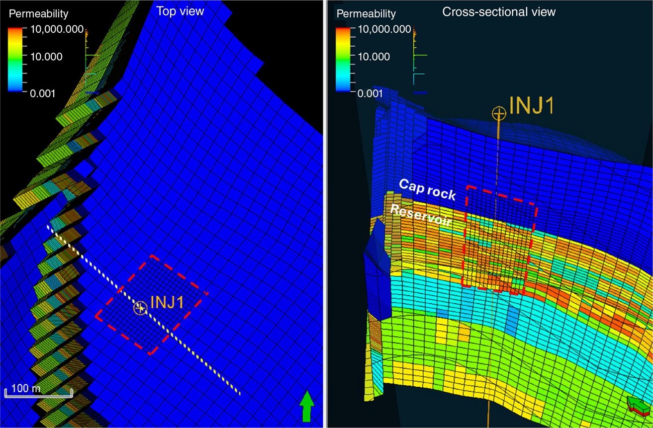
Local grid refinement (LGR) is incorporated into the modelling by increasing the original grid resolution around the injector well by a factor of three (laterally), both in the reservoir and cap rock (Fig. 1). This high-resolution refinement provides a more detailed representation of the complex physical processes occurring in the near-wellbore region, where fluid injection or extraction induces significant changes in pressure, temperature, and stress fields. The remaining, less dynamic parts of the model are kept at the original grid resolution. This approach strikes a balance between model accuracy and computational efficiency.
Reservoir dynamic flow simulation
The geological model of the Naylor Field covers an area of approximately 1.28 km2. The initial geological grid (reference model) contains 610,000 cells with an average cell width of 20 m and an average layer thickness of 1.8 m (Xu 2006). This grid is unsuitable for geomechanical modelling due to inside-out cells, abrupt changes in cell thickness, and the single layering of the Flaxman Formation. Inside-out cells cause numerical instability, while abrupt thickness changes hinder accurate stress distribution. The Flaxman Formation’s vertical resolution is inadequate for assessing cap rock integrity. To address these issues, the grid is modified by aligning cells, simplifying the Naylor Fault, and refining the resolution of the cap rock.
Fluid model
In the modified case involving LGR, the fluid model for simulation initialisation was based on gas composition of 90% CH4 and 10% ethane (C2H6). This is a simplification of the gas composition used in the early history match model. As this study involves injecting H2, CO2, and nitrogen (N2) into the depleted gas reservoir, these components were introduced in the fluid model. The various gas compositions used in dynamic modelling are given in Table 1.
Gas injection modelling setup
The dynamic modelling of gas injection is performed in two stages:
History match stage to simulate historical gas production and define the initial conditions for the gas storage study.
Gas storage stage where thermal simulation is used to model different storage scenarios, including injecting H2, CH4, and CO2 at 1500 rm3/day over 10 cycles of 6-month injection/production. Additional sensitivity is performed for H2 storage at 500 rm3/day over 10 cycles of 6-month injection/production and 500 rm3/day over five cycles of 12-month injection/production.
Wellbore injection temperature modelling
Accurately modelling pressure and temperature gradients in wellbores is critical for dynamic simulation, especially with varying terminal pressures and fluid rates. In our reservoir simulations, the bottomhole arrival temperature of the injected fluid is a key parameter for thermal modelling.
In this study, we use a wellbore steady-state flow simulator to predict bottomhole pressure and temperature in gas injection wells. We assume a vertical injection well with a 9-5/8 inch casing at 500 m, a 5-1/2 inch (17 pounds per foot, ppf) production casing at 2237 m, and a 2-3/8 inch (4.6 ppf) production tubing at 1900 m. It includes a production packer at 1747 m and a perforation interval from 1979 to 1985 m, with a midpoint at 1982 m.
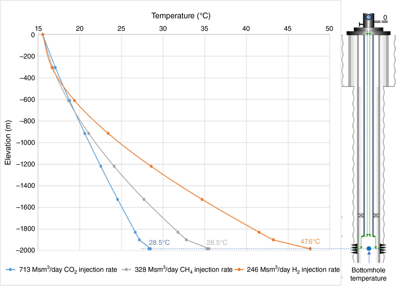
The injection well model is simulated under varying inlet temperatures and gas injection flow rates to determine the resulting bottomhole injection temperature. We assume the inlet temperature of the fluid is at 15.6°C (standard conditions) and the overall heat transfer coefficient is 11.36 J/(s °C m2). Three different injection fluids – CO2, CH4, and H2 – were used for calculating the downhole temperature profiles.
Depending on the injectant type and its properties, the injection rates at surface condition can differ, though the injection rate at reservoir condition is identical. The bottomhole temperature varies with the surface injection rate (Fig. 2). In this case, CO2 has the highest surface injection rate with the lowest bottomhole temperature, followed by CH4 and H2.
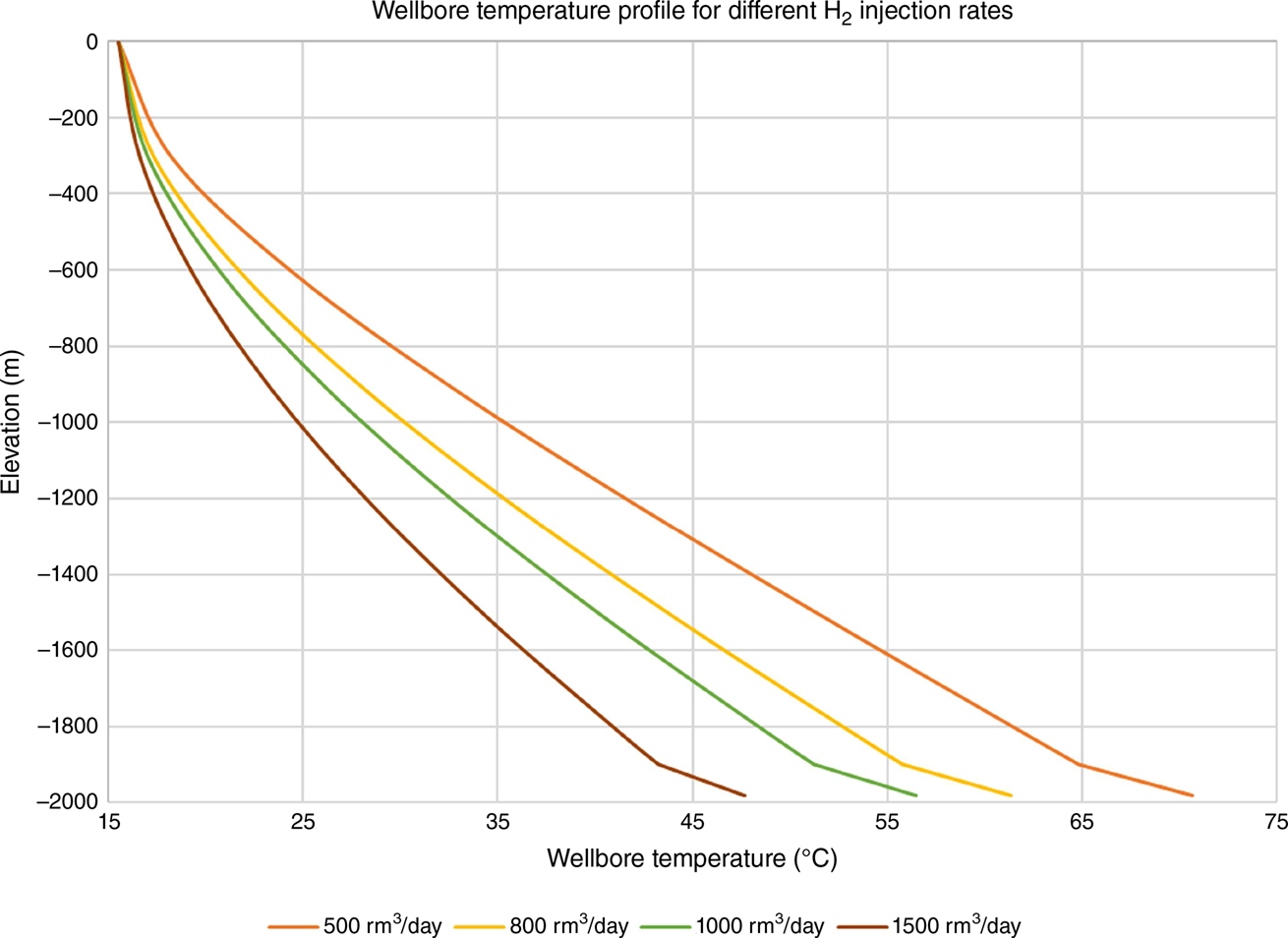
We conducted further sensitivity studies on the effect of rate on the bottomhole arrival temperature. Four injection rates for H2 injection were examined: 500, 800, 1000, and 1500 rm3/day. The results confirm that increasing the injection rate reduces the bottomhole arrival temperature. The temperature traverse plots are shown in Fig. 3, and the graph of bottomhole temperature to injection rate for H2 is shown in Fig. 4.

Heat transfer mechanism in the thermal model
Understanding heat transfer mechanisms is necessary for modelling temperature evolution in a thermal simulator. The primary mechanisms considered are convection and conduction. Convection involves heat transfer through the physical movement of a fluid. Convection occurs in the reservoir when the injected fluid (such as cooler gas stream) interacts with the hotter in situ reservoir fluid. Conduction is heat transfer through direct contact of materials (or molecules) of different temperature, without any movement or flow of the materials. This occurs within the reservoir rock matrix, between reservoir and non-reservoir rocks, and within non-reservoir rocks.
Inclusion of cap rock in the thermal model
In conventional (isothermal) dynamic simulations, fluid flow is modelled solely within reservoir rocks, with non-reservoir rocks treated as non-porous and excluded from the grid. One distinction between thermal and conventional simulation models is the inclusion of non-reservoir rocks, which have heat capacity and conductivity but no fluid content. This study incorporates overburden layers (cap rock) in the thermal simulation grid. Heat transfer occurs in the reservoir system, due to heat conduction and convective fluid flows, while in the cap rock, only heat conduction is simulated.
The injection point, located at the top of the reservoir layer near the reservoir–cap rock boundary, optimises hydrogen withdrawal. The cooler injected gas affects heat transfer near the well, influencing both the reservoir and cap rock above the perforation zone. Modelling cooling in the cap rock is essential for analysing stress and strain changes, which are critical for assessing cap rock integrity. The original model represents the cap rock with a single layer, which is adequate for isothermal simulations but insufficient for thermal simulations aimed at geomechanics assessments. A finer vertical resolution is integrated into the thermal model for accurate cap rock integrity analysis.
For similar reasons, LGR is implemented to enhance the grid resolution laterally around the wellbore, encompassing both the reservoir and cap rock (Fig. 1). This refinement improves the fidelity of pressure and temperature computations.
Rock thermal properties
In thermal simulations, rock thermal conductivity and volumetric heat capacity are defined as inputs to the reservoir simulator. Understanding these properties is essential for predicting the thermal behaviour of the reservoir and surrounding rocks. Volumetric heat capacity defines the amount of heat needed to raise the temperature of a unit volume of rock, while thermal conductivity determines the magnitude and direction of heat flow in response to temperature gradient within the reservoir. Essentially, rocks with lower volumetric heat capacity and higher thermal conductivity will experience greater heat loss compared to rocks with higher volumetric heat capacity and lower thermal conductivity.
In this study, we utilise the thermal properties of sandstone and cap rock outlined by Chekhonin et al. (2012). Due to uncertainties in the properties, they are categorised into two groups for sensitivity analysis (Table 2): high thermal impact (HTI, characterised by lower volumetric heat capacity and higher thermal conductivity) and low thermal impact (LTI, higher volumetric heat capacity and lower thermal conductivity).
Comparison of thermal perturbations of H2, CO2, and CH4
One focus of the study is to compare the thermal perturbations caused by injecting H2, CO2, and CH4 into a depleted gas reservoir. Four scenarios are analysed to cover the range of results: HTI cases for H2 (HTI_H2), CO2 (HTI_CO2), and CH₄ (HTI_CH4), and a LTI case for H2 (LTI_H2). Consistent operational parameters are used to ensure meaningful comparisons: volumetric injection rate at reservoir condition, number of cycles, initial cushion gas (N2) injection, and soaking periods.
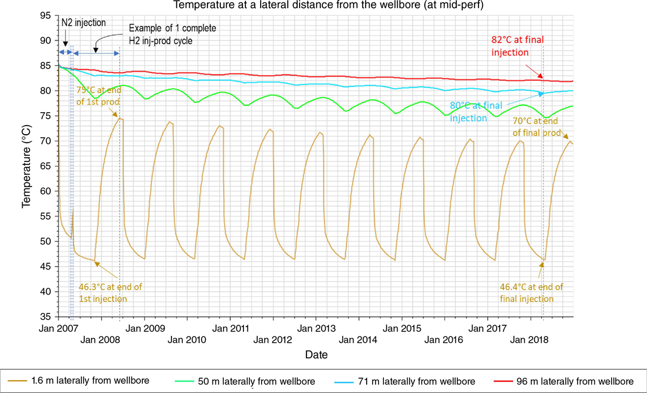
Injecting cold fluids lowers the reservoir temperature near the wellbore. During production, the cooled region reheats, tending to return to the initial temperature (~85°C). Fig. 5 shows temperature fluctuations around the wellbore for HTI_H2, noting a general temperature reduction with each cycle.
Temperature at different lateral distances from the wellbore at mid-perforation depth, for the high thermal impact case (HTI_H2). The cooling effect is reduced away from the wellbore, while overall reservoir cooling increases with time.
Comparing HTI_H2 and LTI_H2, the cold front extends laterally further from the wellbore, reaching ~96 and ~71 m, respectively. Vertically, the cold front in HTI_H2 extends 43 m into the cap rock, compared to 11 m in LTI_H2 (Fig. 6). Heat transfer in the cap rock is slower due to conduction only, whereas heat transfer in reservoir rock also involves convection.
Comparison of H2, CO2, and CH4 temperature (cross-sectional view) at the end of the tenth injection period.
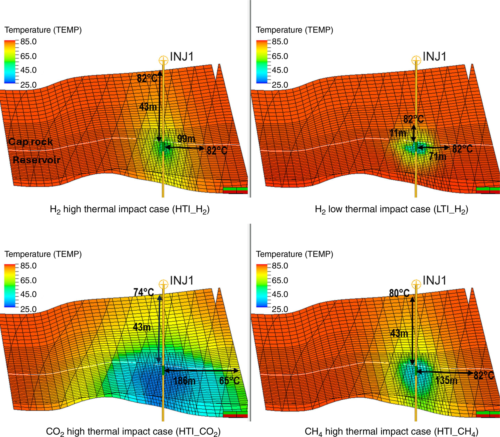
Both HTI_CO2 and HTI_CH4 follow the same operational parameters. Minimum bottomhole temperatures are 23°C (CO2) and 33°C (CH4), colder than 46°C for H2. The tenth injection cycle shows that the lateral cold front extends the farthest for CO2 (>186 m), followed by CH₄ (~135 m) and then H2. Vertically, the CO2 cold front extends the farthest, followed by CH₄ and H2. In the overburden 43 m above the reservoir, temperatures are 74°C (CO2), 80°C (CH₄), and 82°C (H2).
Among the three fluids compared, CO2 causes the most significant thermal perturbation both vertically and laterally, while H2 injection has the lowest thermal impact. Given that identical rock thermal properties (HTI) are used for all three injection scenarios (HTI_H2, HTI_CO2, and HTI_CH4), the modelled thermal perturbation indicates that fluid movement and the thermal properties of the fluid itself influence the extent of the cold front.
Geomechanical simulation
The 3D geomechanical grid for the Naylor Field was constructed by embedding the dynamic reservoir model grid – including LGR around the injector well – with the surrounding overburden, sideburden, and underburden. The total size of the Naylor 3D geomechanical model is 1.3 million cells. The embedment ensures that the geomechanical model accurately captures the interactions between the reservoir and its adjacent geological structures along with the associated loading effects, such as gravitational loading from the overburden and lateral tectonic forces acting on the edge boundary of the sideburden.
The stress boundary condition and the mechanical properties of the 3D geomechanical model were based on the calibrated 1D mechanical earth models developed in previous studies (e.g. van Ruth et al. 2007; Berard et al. 2008; Vidal-Gilbert et al. 2009, 2010; Tenthorey et al. 2010, 2013, 2014). We refer the reader to these studies for a full description of the model and its calibration.
The reservoir and overburden are modelled as elastoplastic materials using the Mohr–Coulomb constitutive model. The 3D mechanical properties are derived from calibrated 1D properties and populated in the 3D grid using porosity, facies, and zonation. Table 3 summarises the 3D mechanical properties of the cap rock and the sand and shale in reservoir. A linear thermal expansion coefficient of 13E−6/°C is used. The stress path coefficient, which correlates changes in stresses to pore pressure changes, is around 0.6 in the reservoir.
| Properties | Reservoir | Cap rock | |
|---|---|---|---|
| Young’s modulus (GPa) | 14.7 ± 3.1 | 8.2 ± 1.8 | |
| Poisson’s ratio (unitless) | 0.22 ± 0.01 | 0.26 ± 0.01 | |
| Friction angle (°) | 28.4 ± 5.3 | 23 ± 1.1 | |
| Unconfined compressive strength (bar) | 359.7 ± 109.6 | 184.3 ± 58.0 | |
| Tensile strength (bar) | 18.0 ± 5.5 | 9.2 ± 2.9 |
Coupled reservoir geomechanics cases
We present selected coupled simulation cases in this paper to highlight the key findings of the study (Table 4). The reference case, HTI_H2, represents the high thermal impact scenario for H2 with an injection rate of 1500 rm3/day over 10 cycles of 6-month injection/production. The comparison cases include variations in thermal impact (LTI_H2 and no thermal, NoDT_H2), fluid type (HTI_CO2 and HTI_CH4), and injection rates (HTI_H2_500CY10 and HTI_H2_500CY5).
| Case name | Fluid | Thermal impact | Rate (rm3/day) | No. of cycles | |
|---|---|---|---|---|---|
| HTI_H2 A | H2 | High thermal impact | 1500 | 10 × 6-months | |
| HTI_CH4 | CH4 | High thermal impact | 1500 | 10 × 6-months | |
| HTI_CO2 | CO2 | High thermal impact | 1500 | 10 × 6-months | |
| LTI_H2 | H2 | Low thermal impact | 1500 | 10 × 6-months | |
| NoDT_H2 | H2 | No thermal impact | 1500 | 10 × 6-months | |
| HTI_H2_500CY10 | H2 | High thermal impact | 500 | 10 × 6-months | |
| HTI_H2_500CY5 | H2 | High thermal impact | 500 | 5 × 12-months |
For the integrated reservoir-geomechanics simulations, a total of 26 coupling steps were selected to capture the full evolution of pressure and temperature fluctuations, focusing on the peak and trough values during the 10 injection and production cycles.
Wellbore fractures risk assessment
Tensile fractures at the wellbore occur when the stress state exceeds the rock’s tensile strength, leading to fracture initiation and propagation. During fluid injection, two opposing forces affect the rock’s stress state: increased pressure raises the total stresses and reduces the effective stresses, while thermal cooling causes poroelastic contraction, reducing both the total and effective stresses and making the rock more susceptible to tensile failure.
In this paper, the risk of wellbore fracturing is assessed by comparing the injection bottomhole pressure to the pressure required to initiate, reopen, and propagate tensile fractures. The fracture initiation (breakdown) pressure is based on the tensile failure criteria: when the minimum effective principal stress reaches the rock’s tensile strength, a crack forms perpendicular to this stress. To reopen an existing tensile fracture, it is assumed that the tensile strength of the rock does not contribute. Fracture initiation and reopening pressures can be higher or lower than the minimum horizontal stress (Shmin) since they relate to near-wellbore stresses and depend on the stress distribution from the far-field to the near-wellbore region. The pressure required to propagate the fracture laterally from the wellbore is assessed based on the fracture growth pressure, FGROW (Ito et al. 2001). Lower fracture pressures increase the risk of fracturing, as less borehole pressure is required to initiate fractures.
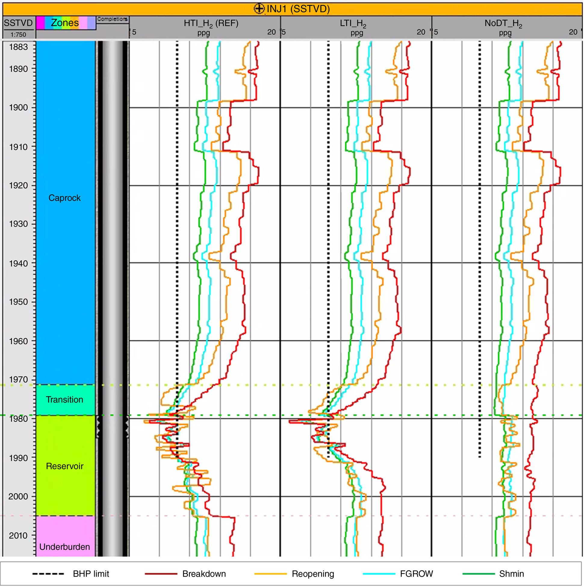
Fig. 7 compares the reference case (HTI_H2) with low thermal impact case (LTI_H2) and no thermal modelling case (NoDT_H2) at the end of the injection cycles. The four curves represent the Shmin, fracture initiation, reopening, and FGROW. The curves are generated based on simulation results, from the end of the 10 injection cycles to capture the worst-case scenario. For hydrogen, the HTI_H2 case produces the lowest fracture pressures compared to the other two cases, due to the effect of thermal cooling. The wellbore fracture risk is high in the reservoir and low in the cap rock. Although the effect of thermal cooling on fracture pressures is less pronounced in the LTI_H2 case, the wellbore fracture risk in both the reservoir and cap rock remains similar to that of the HTI_H2 case. In the NoDT_H2 case, the fracture pressures in the reservoir are higher at the end of injection cycle because they are only influenced by increased reservoir pressure and not by thermal-induced stress reduction, resulting in no risk of wellbore fracturing. This demonstrates that neglecting thermal effects can lead to an incomplete understanding of the stress state and potentially an underestimation of the fracturing risk.
Variation of fracture pressures with depth for the reference H2 high thermal impact case (HTI_H2), H2 lower thermal impact case (LTI_H2), and H2 no thermal case (NoDT_H2) at the end of final injection cycles.
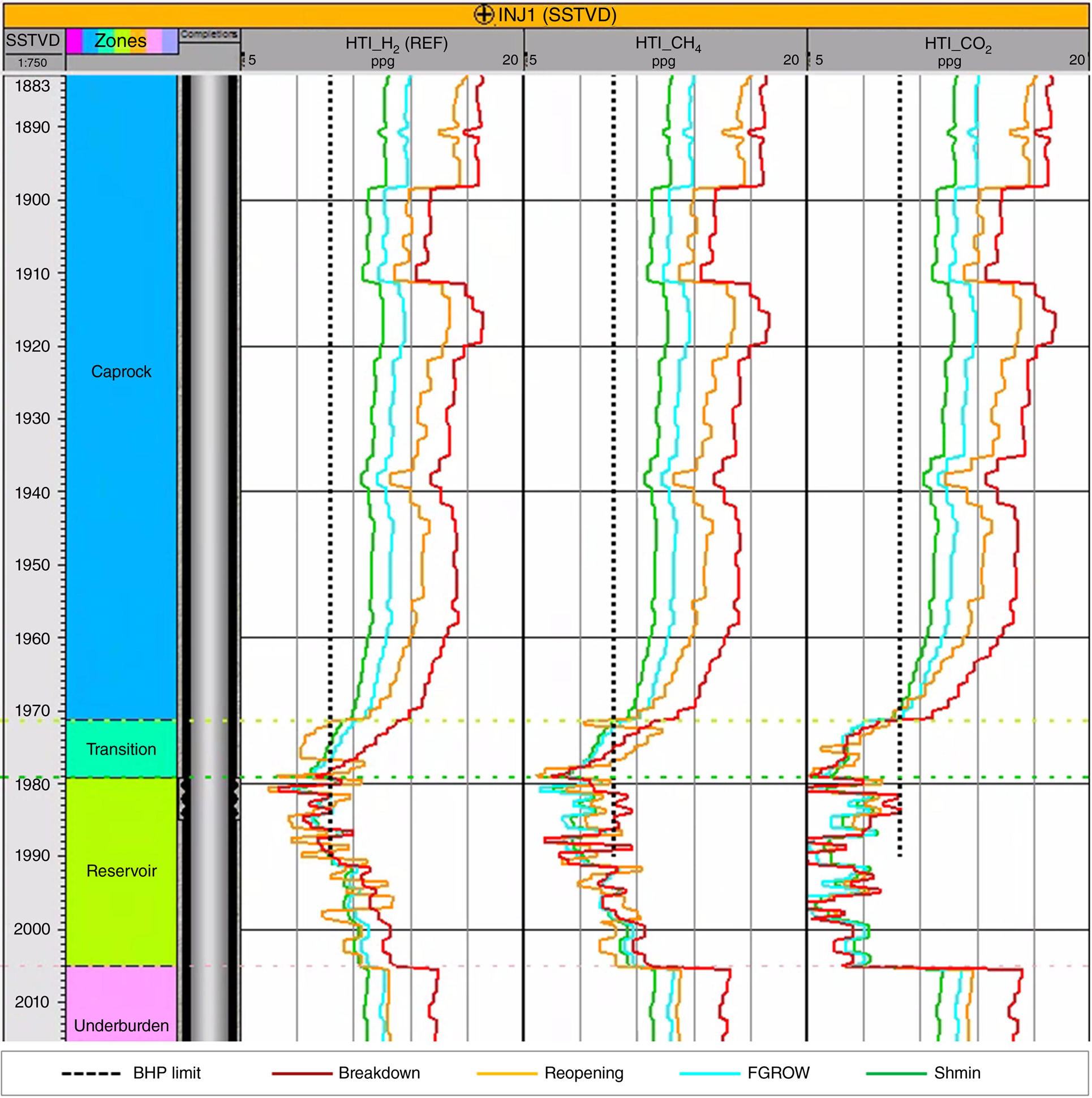
Comparison of the reference case (HTI_H2) with different fluid systems (HTI_CO2 and HTI_CH4) at the end of injection cycles is shown in Fig. 8. The fracture pressures are lowest in the HTI_CO2 case, followed by HTI_CH4. The fracture pressures are lower than the bottomhole pressure in the reservoir rock for all cases and at the base of the cap rock for the HTI_CO2 and HTI_CH4 cases. Although there is a potential risk of generating and propagating tensile fractures in the reservoir, the likelihood of these fractures growing vertically and breaching the cap rock is low. The fracture pressures are highest in the HTI_H2 case, suggesting that the risk of wellbore fracturing in hydrogen storage is lower than in CO2 and CH4 storage.
Variation of fracture pressures with depth for the high thermal impact cases HTI_H2, HTI_CH4, and HTI_CO2 at the end of final injection cycles. The fracture pressures are highest in the HTI_H2 case, suggesting that the risk of wellbore fracturing in hydrogen storage is lower than in CO2 and CH4 storage.
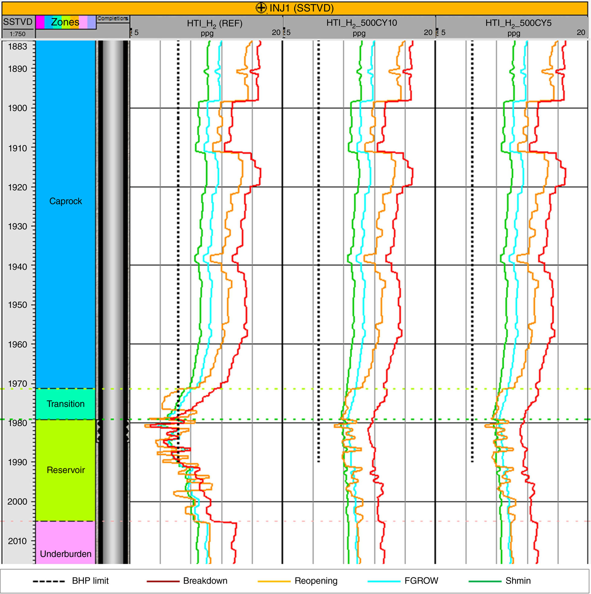
Reducing the injection rate has significant impact on the thermal cooling and the reduction of the wellbore fracturing risk. Fig. 9 presents the comparison between the reference case 1500 rm3/day for 10 cycles of 6-month injection/production (HTI_H2) with the case of 500 rm3/day for 10 cycles of 6-month injection/production (HTI_500CY10) and the case of 500 rm3/day for five cycles of 12-month injection/production (HTI_500CY5). The fracture pressures for both reduced injection rate cases remain higher than the bottomhole pressure which leads to low risk of wellbore fracturing.
Variation of fracture pressures with depth at the end of injection cycles: 10 cycles of 6-month injection/production with injection rate 1500 rm3/day (HTI_H2) and 500 rm3/day (HTI_500CY10), and five cycles of 12-month injection/production with an injection rate of 500 rm3/day (HTI_500CY5). Reducing the injection rate significantly reduced the risk of wellbore fracturing.
Fault reactivation risk assessment
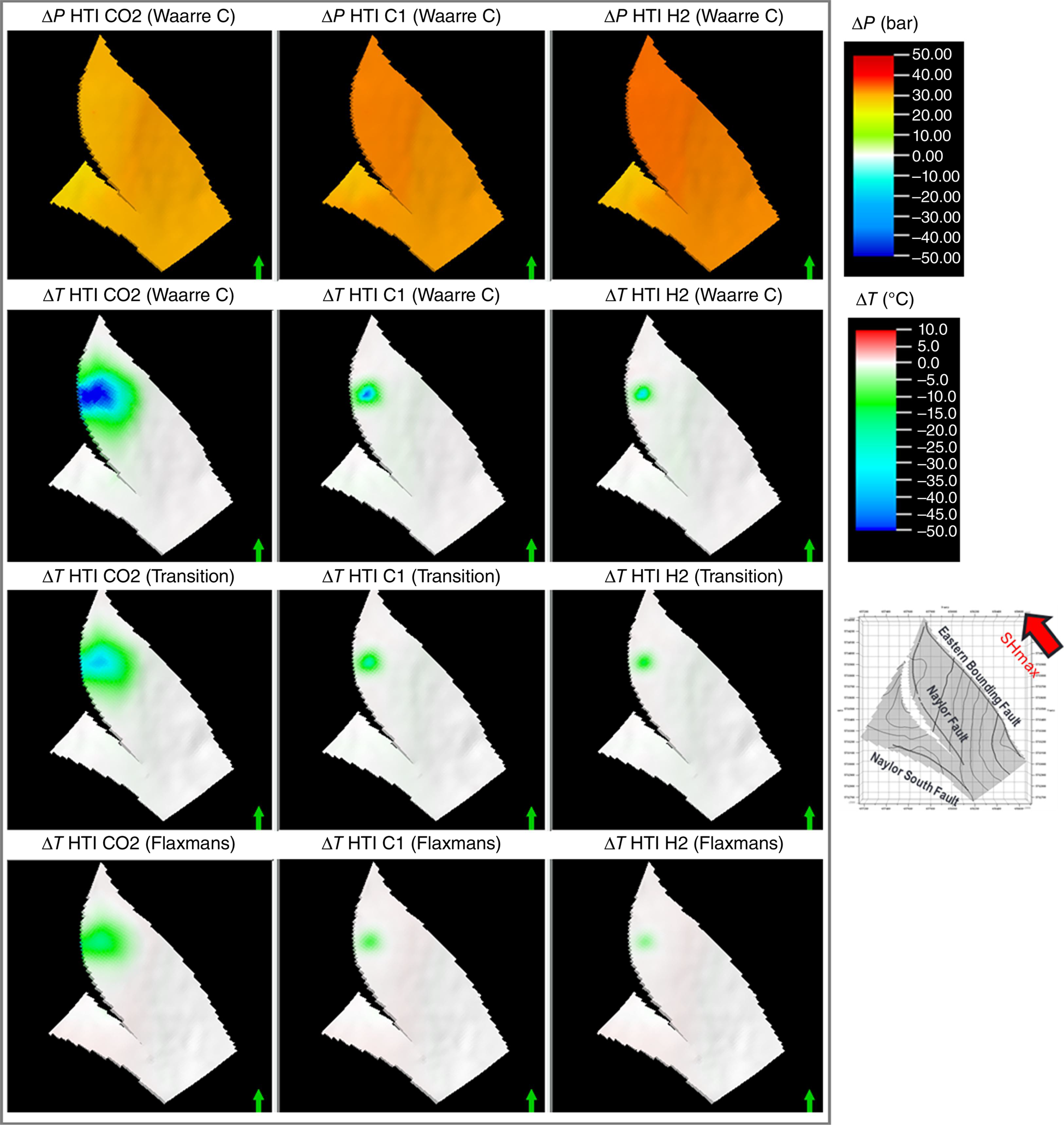
The Naylor Field geomechanical model includes three faults: Naylor, Naylor South, and Eastern Bounding. The Naylor Fault, closest to the injector well, is most impacted by thermal cooling, while the other two faults have minimal exposure. Pressure changes affect all three faults more uniformly due to good reservoir connectivity. Fig. 10 compares delta pressure and delta temperature at the end of the last injection cycle for the reference case HTI_H2 with HTI_CH4 and HTI_CO2.
Comparison of delta pressure and delta temperature at the end of the last injection cycle reference H2 high thermal impact case (HTI_H2, right column), CH4 high thermal impact case (HTI_CH4, middle column), and CO2 high thermal impact case (HTI_CO2, left column). The delta pressures are shown here at the top of the reservoir while the delta temperatures are shown here at the top of the reservoir, transition zone, and the cap rock (Flaxman Formation).
The faults are modelled here using the equivalent material approach, simplifying the complex behaviour by treating the faulted rock mass as a homogeneous material with adjusted equivalent properties that account for both intact rock and fault material. It incorporates constitutive relationships to describe the deformation and failure of both intact rock and fault material, allowing for relative displacements across the fault plane to be interpreted as continuous strains. This method represents faults without explicitly modelling the discontinuities, making it computationally efficient and easier to implement in numerical simulations.
Fault reactivation risk is assessed based on the accumulated plastic shear strain on the faults at the end of the simulation. Fault plastic shear strain is the permanent deformation due to opposing forces parallel to the fault surface. Higher plastic shear strain indicates a higher risk of fault slipping. Fig. 11 presents the fault plastic shear strain for the Naylor Fault, the fault closest to the injector well with the most exposure to thermal cooling. This figure shows a comparison between the reference case (HTI_H2) with different fluid systems (HTI_CH4 and HTI_CO2), different rates (HTI_H2_500CY10 and HTI_H2_500CY5), and no thermal (NoDT_H2) cases.
Comparison of fault plastic shear strain in Naylor Fault at the end of simulation. Cases with 10 cycles of 6-month injection/production: (a) H2, high thermal impact, 1500 rm3/day; (b) H2, no thermal effect, 1500 rm3/day; (c) CH4, high thermal impact, 1500 rm3/day; (d) CO2, high thermal impact, 1500 rm3/day; and (e) H2, high thermal impact, 500 rm3/day. Case (f) H2, high thermal impact, 500 rm3/day used five cycles of 12-month injection/production.
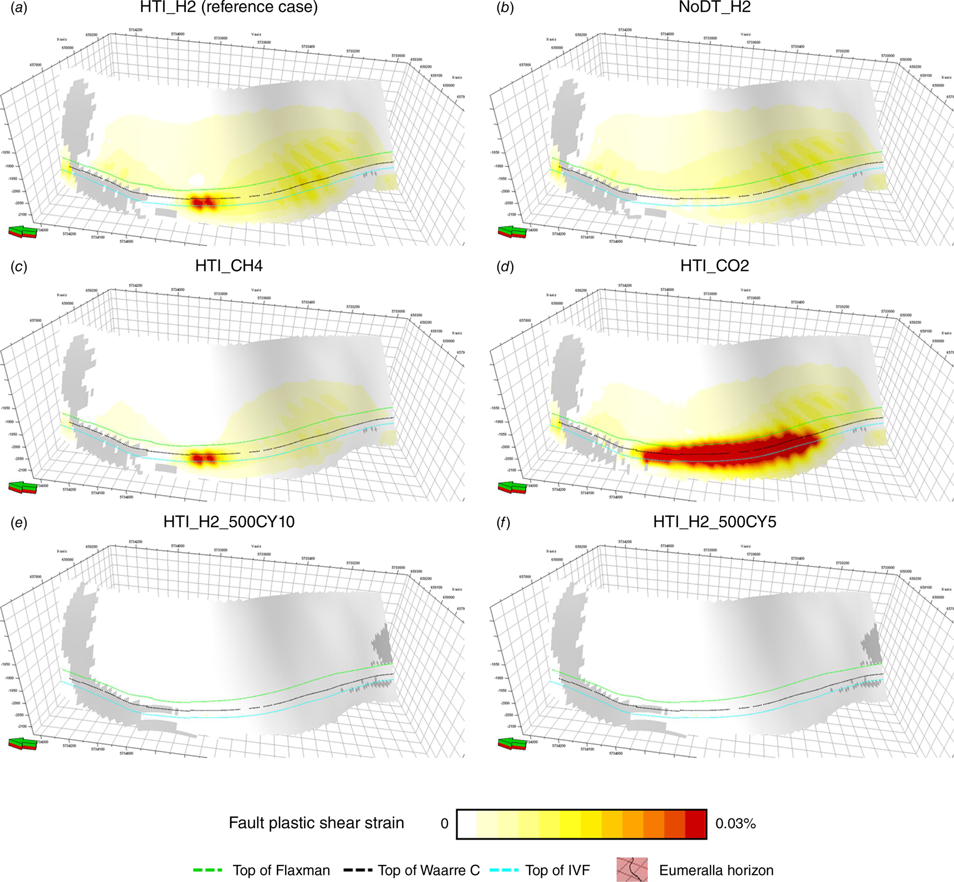
The HTI_CO2 case has the highest fault reactivation risk due to the significantly lower temperature. There is negligible fault plastic shear strain in the NoDT_H2 case, showing the danger of underestimating the fault reactivation risk when thermal cooling is excluded. The fault reactivation risk of the HTI_CH4 case is similar to the HTI_H2 reference case, likely because the higher field pressure offsets the lower temperature in the HTI_CH4 case.
Most yielding occurs during the first injection when faults are subjected to the greatest pressure and temperature load in comparison to the load condition during the history match (field production) period. The fault section that is high angle and aligned with the maximum horizontal stress is most susceptible to failure. The highest fault yielding occurs in the Waarre Formation, indicating medium to high fault reactivation risk in the reservoir. In the cap rock, the fault reactivation risk is low to medium for the HTI_H2 and HTI_CH4 cases, and medium to high for the HTI_CO2 case.
Reducing the injection rate can significantly reduce the fault reactivation risk. Lowering the rate from 1500 to 500 rm3/day dampens both the temperature and pressure effects and leads to a low fault reactivation risk in both the reservoir and the cap rock.
Discussion
The role of injection-related thermal effects in the subsurface and the resulting effects on the geomechanical state has received greater attention in recent years, particularly for CO2 storage projects, where increasing injection targets are leading to greater thermal cooling in the subsurface. In this paper, we show that H2 injection and storage introduce less severe thermal cooling compared to CO2 or CH4 under the same boundary conditions and reservoir injection rate. This is due to H2’s thermal properties and its slower surface injection rates, giving H2 more time for heat exchange with the rock. This study compares the risks imposed by different volumetric injection rates but does not address the risks associated with variations in mass injection rates. Future study could include comparisons of mass injection rates, as the lower density of H2 compared to CO2 and CH4 means that larger volumes of H2 would be injected to achieve the same mass rate, thereby may impact geomechanical risks differently relative to the other two gases.
Despite H2’s lesser impact on thermal effects, every site and project will differ, necessitating the assessment and modelling of injection-related thermal disturbances. Figs 3 and 4 show that reservoir cooling will depend on the injection rate, with higher rates causing greater cooling. Additionally, reservoir depth will also influence cooling. Every project will therefore have its own unique geomechanical response resulting from injection related cooling. If harmful thermally-induced geomechanical effects are predicted, adding more injection wells and injecting at a correspondingly lower rate can maximise H2 heat exchange in the wellbore before entering the reservoir formation.
In this paper, the risk of wellbore fracturing is assessed by comparing the injection bottomhole pressure to the rock fracture pressures, providing an initial evaluation of tensile fracture risks but not fully capturing hydraulic fracturing behaviour. Comprehensive modelling requires a hydraulic fracture simulator coupled with a geomechanics simulator for accurate representation of fracture initiation, growth, and conductivities, providing a detailed understanding of fracturing risks during underground storage injection.
This work does not include changes in fault transmissibility due to fault slip or its impact on fault reactivation risk. Fault transmissibility can significantly affect fluid flow, pressure distribution, and rock stress state. Future improvements could involve a two-way coupling scheme in which the geomechanics simulator updates the fluid flow simulator on changes in fault transmissibility due to fault strains. This would enable more dynamic and realistic fault modelling under varying stress conditions, leading to more accurate predictions of fault reactivation risk.
We demonstrate that wellbore fracturing and fault reactivation risks can be managed by adjusting the injection rate. Future studies would benefit from recent software developments for efficient integrated 4D geomechanical risk assessment during simulations rather than post-processing analysis (Haas et al. 2024; Yoon et al. 2024). This fully-coupled approach would enable dynamic control of injection rates in the fluid flow simulator, based on predefined limits and criteria, to optimise the injection strategy without compromising underground storage safety.
Conclusions
The work presented in this paper focuses on investigating the fluid dynamics and geomechanical implications of underground H2 storage, comparing it with the well-researched CO2 and natural gas storage. Local grid refinement around the injector well has been useful in providing high-resolution results in the wellbore region where there are significant changes in pressure and temperature. Importantly, a combined approach where flow simulation with thermal modelling is included to account for the cooling effect of injecting cold fluid into a hot reservoir, which leads to rock contraction and increased susceptibility to failure.
For the same reservoir injection rate, H2 storage has a smaller thermal footprint compared to CH4 and particularly in comparison to CO2 storage. This results in higher fracture pressures for H2 storage, suggesting a lower risk of wellbore fracturing compared to CO2 and CH4 storage. The risk of wellbore fracturing and fault reactivation is highest for CO2 storage due to the larger thermal cooling. The fault reactivation risk for CH4 storage is similar to that of H2 storage. It is likely that the higher field pressure offsets the lower temperature in CH4 storage compared to H2 storage.
Reducing the injection rate dampens both temperature and pressure effects, subsequently reducing the risk of wellbore fracturing and fault reactivation. We have demonstrated the importance of including thermal modelling in underground gas storage with significant cooling. Failure to do so may lead to an incomplete understanding of the stress state and an underestimation of geomechanical risks.
Data availability
The data that support this study will be shared upon reasonable request to the corresponding author.
Declaration of funding
This project was supported by the Australian Government’s ‘Exploring for the Future’ program (2016–2024).
Acknowledgements
This work is part of the former Australian Government’s ‘Exploring for the Future’ program, which was led by Geoscience Australia. We are thankful to CO2CRC Ltd and Tess Dance and Jonathan Ennis-King at CSIRO for providing the base models and other data from the Otway site that were used in this study. This paper is published with the permission of the CEO of Geoscience Australia.
References
Berard T, Sinha BK, Van Ruth P, Dance T, John Z, Tan CP (2008) Stress Estimation at the Otway CO2 Storage Site, Australia. Paper presented at the SPE Asia Pacific Oil and Gas Conference and Exhibition’ Perth, Australia. Paper no. SPE-116422-MS. 10.2118/116422-MS
Chekhonin E, Parshin A, Pissarenko D, Popov Y, Romushkevich R, Safonov S, et al. (2012) When Rocks Get Hot: Thermal Properties of Reservoir Rocks. Oilfield Review 24, 20-37.
| Google Scholar |
Feitz A, Radke B, Ricard L, Glubokovskikh S, Kalinowski A, Wang L, et al. (2022) The CO2CRC Otway shallow CO2 controlled release experiment: fault characterization and geophysical monitoring design. International Journal of Greenhouse Gas Control 118, 103667.
| Crossref | Google Scholar |
Haas M, Al-Hamad N, Heiland J, Hussein AM, Shekhar S, Srivastava DN, Ramon J, Abdel-Basset M, Al-Anzi A, Al-Ajmi M (2024) 4D Geomechanics New Modelling Approach using Machine Learning Predictions for Giant North Kuwait Jurassic Field. Paper presented at the International Petroleum Technology Conference, Dhahran, Saudi Arabia. Paper no. IPTC-23417-MS. 10.2523/IPTC-23417-MS
Haese R, La Force T, Boreham C, Ennis-King J, Freifeld B, Paterson L, Schacht U (2013) Determining residual CO2 saturation through a dissolution test—results from a CO2CRC field experiment. Energy Procedia 37, 5379-5386.
| Crossref | Google Scholar |
Ito T, Zoback M, Peska P (2001) Utilization of Mud Weights in Excess of the Least Principal Stress to Stabilize Wellbores: Theory and Practical Examples. SPE Drilling & Completion 16, 221-229.
| Crossref | Google Scholar |
Jackson S, Gunning J, Ennis-King J, Dance T, Pevzner R, Dumesny P, et al. (2024) Tracking a subsurface CO2 plume with time-lapse pressure tomography in the Otway Stage 3 field project. International Journal of Greenhouse Gas Control 133, 104099.
| Crossref | Google Scholar |
Jenkins CR, Cook PJ, Ennis-King J, Undershultz J, Boreham C, Dance T, et al. (2012) Safe storage and effective monitoring of CO2 in depleted gas fields. Proceedings of the National Academy of Sciences of the United States of America 109(2), E35-E41.
| Crossref | Google Scholar | PubMed |
Pevzner R, Urosevic M, Popik D, Shulakova V, Tertyshnikov K, Caspari E, et al. (2017) 4D surface seismic tracks small supercritical CO2 injection into the subsurface: CO2CRC Otway Project. International Journal of Greenhouse Gas Control 63, 150-157.
| Crossref | Google Scholar |
Tenthorey E, Vidal-Gilbert S, Backé G, Puspitasari R, Pallikathekathil Z, Maney B, Dewhurst D (2013) Modelling the geomechanics of gas storage: a case study from the Iona gas field, Australia. International Journal of Greenhouse Gas Control 13, 138-148.
| Crossref | Google Scholar |
Tenthorey E, Dance T, Cinar Y, Ennis-King J, Strand J (2014) Fault modelling and CO2 migration potential associated with the CO2CRC Otway 2C injection experiment. International Journal of Greenhouse Gas Control 30, 72-85.
| Crossref | Google Scholar |
Tenthorey E, Hsiao WM, Puspitasari R, Giddins M, Pallikathekathil Z, Dandekar R, Suriyanto O, Feitz A (2024) Geomechanics of hydrogen storage in a depleted gas field. International Journal of Hydrogen Energy 60, 636-649.
| Crossref | Google Scholar |
Vidal-Gilbert S, Tenthorey E, Dewhurst D, Ennis-King J, van Ruth P, Hillis R (2010) Geomechanical analysis of the Naylor Field, Otway Basin, Australia: implications for CO2 injection and storage. International Journal of Greenhouse Gas Control 4, 827-839.
| Crossref | Google Scholar |
Yoon S, Prioul R, Bailey WJ, Birchwood R, Rodriguez-Herrera A, Stefani J (2024). Assessing CO2 Leakage Risks and Fault Stability: A Coupled Flow and Geomechanics Simulation with Uncertainty Analysis of Fault Properties. Paper presented at the 58th US Rock Mechanics/Geomechanics Symposium, Golden, Colorado, USA. Paper no. ARMA 24-772. 10.56952/ARMA-2024-0772
Ratih Puspitasari is a Senior Geomechanics Engineer at SLB in Australia. She holds a Master of Petroleum Engineering from Curtin University. With over 20 years of experience in the oil and gas industry, Ratih has worked in various areas, including cementing, stimulation, reservoir, and production. For the past 15 years, she has specialised in geomechanics, applying her expertise to a wide variety of applications such as drilling optimisation, methane hydrate modelling, and sanding analysis. Her current interests include 3D geomechanical modelling, carbon capture, and unconventional reservoirs. |
Hsiao Wun Moh graduated with a Bachelor’s Degree in Engineering from Universiti Teknologi Malaysia in 2001 and subsequently joined SLB. With more than 20 years in the energy industry, he has worked in Canada, Malaysia, and is presently based in Australia. He began his career as a Wireline Field Engineer and has since transitioned to his current role as Senior Reservoir Engineer. His expertise includes formation testing, downhole fluid sampling, production logging interpretation, and reservoir simulation. He is experienced in field development planning for conventional reservoirs and, more recently, in carbon capture and storage (CCS) over the past few years. |
Eric Tenthorey is a Senior Researcher at Geoscience Australia, with expertise in geomechanics, carbon capture, and other low carbon geoscience disciplines. He holds a PhD from Columbia University and subsequently worked as a researcher at the Australian National University. In 2007, he was engaged by Geoscience Australia to work as a geomechanics expert, focused on developing and proving up CCS technology. More recently, his work has centred on other low carbon geoscience sectors, such as the hydrogen energy future, geothermal energy, and CO2 storage in residual oil zones. |
Zachariah John Pallikathekathil graduated from the Indian Institute of Technology Delhi in Mechanical Engineering. He has held technical and management positions in wireline and logging-while-drilling log acquisition and interpretation. His passion for geomechanics and its multi-disciplinary requirement drew him into the field of geomechanics 15 years ago. He is currently involved in rock testing design, construction of 1D and 3D mechanical earth models for addressing issues on wellbore stability (drilling), completion integrity (sanding, casing), compaction–subsidence, and fault stability over the life of the field for oil and gas reservoirs and CCS projects. He is a member of SPE and was the past President of the SPWLA chapter in Australia in 2010 and 2011. |
Rashmin Dandekar is a Reservoir Engineer at SLB with over 32 years of experience in the upstream oil and gas industry. He holds a Master’s Degree in Petroleum Engineering from Texas A&M University. Throughout his career, Rashmin has specialised in several key areas of reservoir engineering, including reservoir management, reservoir characterisation and modelling, dynamic simulation, field development planning, uncertainty and risk analysis, reserves estimation, and classical reservoir engineering. Currently, he is focused on various aspects of subsurface storage of CO2 and hydrogen, including fluid modelling, thermal modelling, and related areas. |
Marie Ann Giddins is an Advisor in Reservoir Engineering, based in SLB’s Abingdon Technology Center in the UK. She has a BA in Mathematics from the University of Oxford and MSc in Operational Research from the University of Sussex, plus over 30 years of experience in the energy industry. Marie Ann provides technical advice to SLB and clients on reservoir simulation software, workflows, and integrated studies. Her areas of expertise include advanced reservoir engineering applications such as enhanced oil recovery (chemical enhanced oil recovery, miscible injection, and thermal studies), unconventional reservoirs, and non-Darcy flow in gas condensate fields. Her current focus is on new energy, including subsurface studies of CO2, hydrogen, geothermal reservoirs, and critical minerals. She is a mentor and coach for trainees and experienced engineers at all stages of professional development and has supervised over 80 student intern projects. |
Olivia Suriyanto is a Reservoir Engineer with experience in formation testing, downhole fluid analysis, production logging, reservoir simulation, wellbore stability analysis, and wireline logging operations. She holds a Master of Petroleum Engineering from Curtin University (Australia), and a Bachelor of Chemical Engineering from Gadjah Mada University (Indonesia). Olivia was previously a Senior Reservoir Engineer with SLB’s asset consulting team, focusing on reservoir simulation for oil and gas application, CCS, and underground gas storage. Her current interests are still related to new energy and energy transition, combined with an ongoing data science course, and with a dash of crafting and writing. |
Andrew Feitz is an Environmental Engineer and Director of Low Carbon Geoscience and Advice at Geoscience Australia. He holds a PhD from UNSW and worked as a senior researcher in air and water treatment technologies at UNSW and the Karlsruhe Institute of Technology (Germany). He moved to Canberra in 2008 and joined Geoscience Australia where he developed and led a research program to evaluate monitoring techniques for geological storage of carbon dioxide. Andrew leads Geoscience Australia’s efforts supporting establishment of a hydrogen industry in Australia and was a member of the Advisory Group for the 2024 National Hydrogen Strategy. |