

Case study: successful disconnection of a traditional floating production storage and off-loading unit
Sashi Gajula A C and Bertrand Peuchot BA Eni Australia, 226 Adelaide Tce, Perth, WA 6000, Australia.
B 1120 Hay Street, West Perth, WA 6005, Australia.
C Corresponding author. Email: sashi.gajula@eni.com
The APPEA Journal 58(1) 72-83 https://doi.org/10.1071/AJ17080
Submitted: 27 November 2017 Accepted: 16 February 2018 Published: 28 May 2018
Abstract
Decommissioning a producing asset within a low oil-price market scenario with a possibility of resuming production at a later stage is becoming a frequent task. The main objective of the offshore campaign is to release the floating production storage and off-loading unit (FPSO) at the earliest time by disconnecting all production risers, umbilical and mooring chains, and ensuring integrity of the subsea assets for future use.
The entire project for the disconnection of this FPSO was managed in four phases. The first two phases were related to shutdown of production and FPSO clean-up. The FPSO readiness for disconnection was required before the final two phases: disconnection of risers and mooring lines.
Detailed engineering was carried out in consultation with various stakeholders involved in the project: the regulator, the company, the FPSO owner and the installation contractor. Through feasibility studies, the best option was selected, which included innovative solutions to reduce overall offshore duration and project costs. The project was successfully completed by meeting the key objective of early departure of the FPSO without lost time injury or any significant environmental incidents.
Keywords: gate valve intervention tool, pre-decommissioning.
Introduction
The Floating Production Storage and Off-loading Unit (FPSO) was located in the Timor Sea approximatively 500 km off the Australian coast. The field comprises three subsea production wells at water depths of ~300–450 m. These wells were tied back to an internal turret in the FPSO which was moored within 325 m of water depth.
Subsea wells were controlled by an electrohydraulic control system. The electrohydraulic control system comprised a main umbilical starting from the FPSO and terminating at the Umbilical Termination Assembly (UTA). The UTA was connected to a Subsea Distribution Unit (SDU) by means of electrohydraulic flying leads. Two infield umbilicals were connected to the SDU and to the subsea horizontal Christmas trees (HXT). The third subsea tree was connected to the SDU by means of electrohydraulic flying leads.
Key milestones achieved during FPSO decommissioning were:
-
Zero lost time injury (LTI) and no significant environmental incidents
-
Project completed within schedule and budget
-
Integrity requirements of the subsea assets were achieved and were ready for future use.
Decommissioning and abandonment approach
All operations related to the decommissioning campaign were designed and carefully planned, keeping the following factors in mind:
-
Environmental impact
-
Emission and energy consumption
-
Health and safety
-
Public acceptability
-
Technical feasibility
-
Cost optimisation.
This decommissioning project has been managed through the following main steps:
-
Step 1: Decommissioning detailed engineering is aimed at selecting the best decommissioning option.
-
Step 2: All preparatory activities are carried out for making the facilities ‘hydrocarbon free’. Achievement of this milestone marks the end of operations and the handover of responsibilities from the operations to the decommissioning team.
-
Step 3: Decommissioning execution activities have to be planned in accordance with local regulation and permit requirements.
FPSO Decommissioning Project
The FPSO Decommissioning Project was carried out in four phases:
-
Phase 1 – pre-disconnection campaign: activities such as cessation of production, inflow test the surface controlled sub surface valve (SCSSV), bullhead the well, flushing of all flowlines (to 30 ppm) and test HXT to establish two independent well barriers
-
Phase 2 – preparation for disconnection: activities such as preparation of the FPSO for disconnection (clean-up of topsides, installation of pull-in heads, disconnecting topside spools, purging and gas free of the FPSO)
-
Phase 3 – riser and umbilical disconnection: disconnection of the six risers and one umbilical from the FPSO
-
Phase 4 – mooring line disconnection: disconnection of the mooring system (six chains) and FPSO sail-away.
Figures 1 and 2 illustrate Kitan field overview and the FPSO layout.

|

|
Phase 1 - pre-decommissioning campaign
The pre-disconnection campaign commenced after the cessation of production. Relevant personnel and equipment were mobilised to the FPSO topside before shutdown of production. The main steps of the pre-disconnection phase were:
-
Shutdown of production
-
Inflow test of the SCSSV
-
Lubricate and circulate all gas out of the well annulus using treated seawater with chemical inhibitor
-
Flush all flowlines to 30 ppm of hydrocarbon or less using treated seawater with chemical inhibitor
-
Pressure test the HXT valves to confirm the integrity of two independent tested barriers.
Phase 2 – preparation for disconnection
The FPSO Operation Crew was responsible for riser winch certification for re-use and operational readiness before the arrival of marine vessels. Pre-disconnection activities consisted of:
-
FPSO heading to be in line with the heading of control tugs
-
Disconnection and removal of topside spools
-
Testing of subsea pressure barriers
-
Ballasting of FPSO
-
Flushing of flexible lines
-
Riser winch sheave installation
-
Functional check and operation of riser winch.
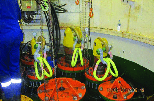
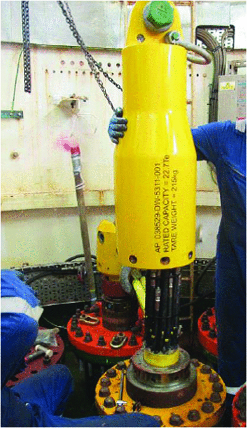
Once the above listed activities were completed by the FPSO crew, the disconnection contractor carried out the following activities:
-
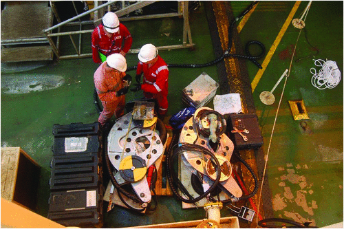
Mobilisation and preparation of the pull-in equipment on board the FPSO (Fig. 3)
-
Installation of umbilical pull-in can
-
Installation of the riser pull-in heads (Fig. 4)
-
Setup sheave and route FPSO winch wire over correct riser
-
Fit pull-in heads to risers
-
Terminate umbilical pig tails and fit pull-in head.
|
|
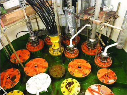
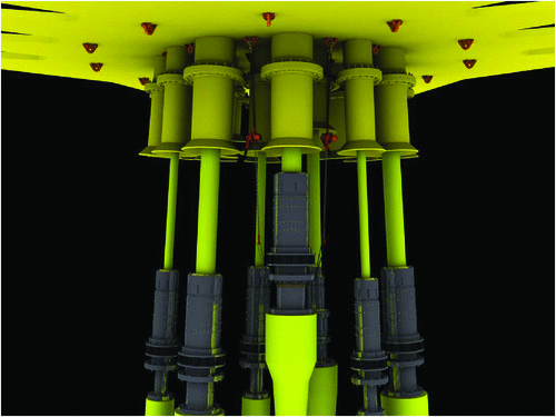
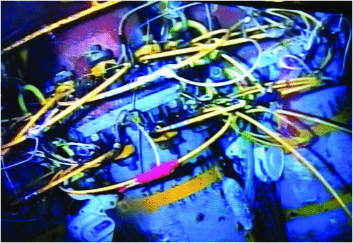
Riser and umbilical pull-in head installation
The Figures 3 and 4 below show the ‘as found’ FPSO turret before starting the activities and post-installing the pull-in heads on risers ‘end assembly’.
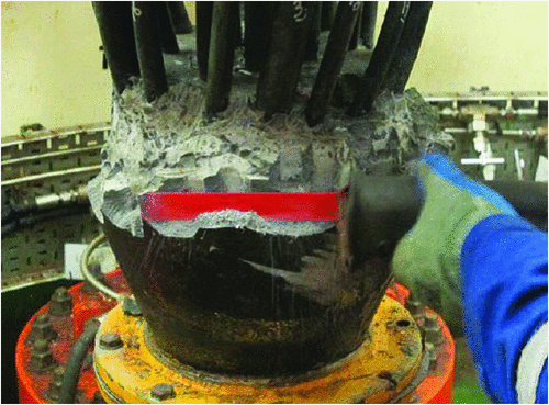
In order to install the umbilical pull-in heads, it was necessary to remove the resin around the termination. This activity provided access for connecting end-fittings and installation of the pull-in heads as shown in the figures below (Figs 5 and 6).
|
|
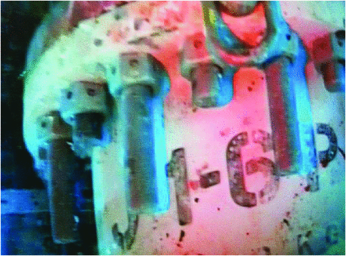
Closing of subsea production master and wing valves
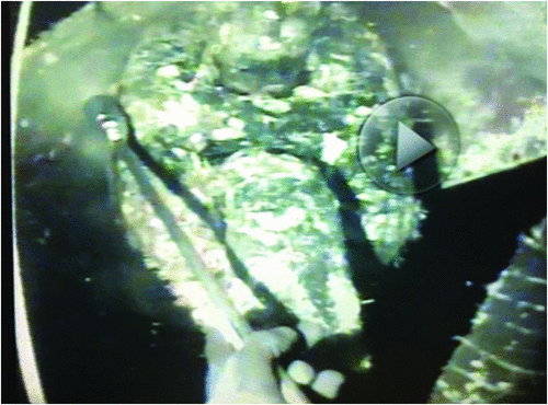
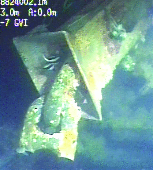
During the pre-decommissioning campaign it was not possible to confirm the pressure integrity of two Christmas tree valves on the HXT (Fig. 7). A remotely operated vehicle (ROV) survey confirmed that two valves were not in the fully closed position.

|
As per company standards and international best practices, a double barrier was required to ensure the integrity of HXTs before disconnection of the FPSO from the field. This operation was achieved through a manual override of the valves using a gate valve intervention tool (GVIT). As a contingency, another option was to disconnect the flowlines with the help of an ROV connector and then connect a pressure-rated blind flange via a Grayloc clamp.
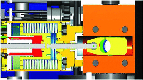
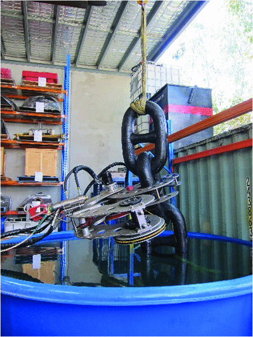
The manual override option required the fabrication of a GVIT (Figs 8 and 9) specially designed to override the spring-loaded actuator and fully close the M3000 gate valve by applying a pull force to the gate valve stem end-cap using hydraulic cylinders supplied from a ROV hot stab connection.
|

|
The manual override option utilising the GVIT (Figs 8 and 9) was chosen as the first option and proved to be successful in closing both tree valves (Fig. 7) in less than 24 hours. This work was performed by ROV from the construction vessel.
Phase 3 – riser and umbilical disconnection
Diving operations were undertaken by a dive support vessel moored against the starboard side of the FPSO. Diving operations were carried with experienced manning on-board along with the coordination team from the FPSO.
All diving activities were carried out without any major issues or equipment breakdown. There were five steps in the dive program:
-
Set up/general visual inspection of turret underside work area.
-
High-pressure water cleaning of work area, including latching mechanisms, bend stiffeners, top section of flow lines under bend stiffeners, padeyes under turret, chain catchers and chains below the chain catchers.
-
Disconnection of risers and umbilicals.
-
Abandonment of risers and umbilicals on seabed.
-
As-left survey and recovery of all under-turret equipment.
High-pressure water cleaning
Appropriate areas were cleaned with a 5000-psi pressure water blaster system and hand scrapers. Hand cleaning was utilised as a contingency method only when the water blaster was unavailable. Marine growth was removed easily with the high-pressure water blaster along with the hand scrapers. Divers had minor issues during chain cleaning due to the small surface area for the diver to brace on while conducting the cleaning.
The following figures (Figs 10 and 11) show the status of marine growth on the bend stiffener latching mechanisms (BSLMs) during the initial inspection and post cleaning.

|
|
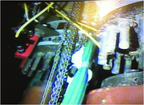
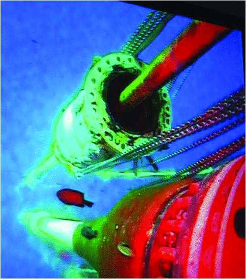
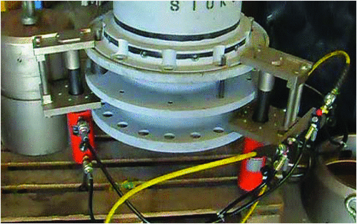
Disconnection of risers and umbilicals
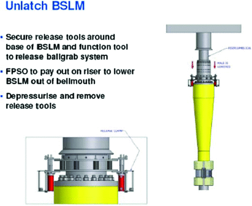
The flowlines within the FPSO turret location consisted of three 6ʹ production and three 2ʹ gas lift lines, plus an electrohydraulic control umbilical. These flowlines were connected to the FPSO turret via a ballgrab-type BSLM. The umbilical was connected to the turret via a hydraulically operated diverless BSLM.
Prior to disconnection of the BSLM, divers installed hold-back arrangements to ensure that the bend stiffeners do not slide along the riser length.
Disconnection of flowline BSLMs was planned to be conducted as per the manufacturer’s procedure. The following figures show the sequence of the operations (Figs 10–20).
|
|
|
|
|
|
|

|
|
However, the tool planned to release the ballgrab connector inside the BSLM did not work as effectively compared with onshore testing carried out during initial planning stages.
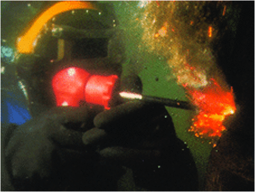
Contingency disconnection methods
Three contingency methods were planned in the event of disconnection failing during actual operations.
Contingency 1: Use of Hydratight jacks on the bolts joining the female BSLM to the turret J-tubes. Jacks and equipment were supplied to enable up to ‘100%’ press. The process of transferring large numbers of jacks restrained the fitting of jacks and the absence of a work basket made the Hydratight contingency method tedious and inefficient (Figs 14–18).
Contingency 2: Use of a hydraulic ‘nut-splitting’ tool designed to work on individual nuts. This proved ineffective due to access issues, damage to splitter blades, off-centre cuts and when two opposing cuts on nuts were required there were difficulties in accessing some nuts located between J-tubes (Fig. 19).
Contingency 3: Subsea oxy arc cutting (Broco) was accepted as a proven method to remove the bolts. BSLMs were removed using Broco on bolts within 15 h of dive time. As a precaution, a second diver monitored any gas build-up during the operation to mitigate any risk of underwater explosion (Fig. 20).
Umbilical disconnection
The planned umbilical disconnection was in line with factory-designed procedure.
All tubes and cables were properly sealed individually and inserted in a waterproof head before abandonment.
Riser and umbilical abandonment on seabed
Once the bend stiffener connectors were disconnected, the riser catenary weight was lowered to crosshaul depth using the FPSO winch. The recovery winch from the construction vessel (Fig. 21) was transferred using an ROV. A second ROV was kept on the touchdown point to ensure the catenary of the riser was in the acceptable limits.
|
Following transfer of the riser load to the construction vessel, the riser was recovered and transferred through the vertical lay system (VLS) tower and onto the recovery reel. Buoyancy modules were removed in the work station. Once the last buoyancy module was removed, the riser was laid along the agreed abandonment route on the seabed using the VLS (Fig. 22).
|
The abandonment of the riser on the seabed was carried out in accordance with a pre-established lay table and along a designated track. The flowline and umbilical abandonment was performed under constant ROV monitoring.
Phase 4 – mooring line disconnection
Divers were used to clean the mooring chain and chain catcher in preparation for the ROV operations.
No moorings were cut before all risers and umbilicals were disconnected and laid in the abandonment lay routes. A mooring disconnection sequence was engineered in the initial planning stages. The key governing criteria were that one leg from each section within the turret was disconnected first, followed by the second leg disconnection from opposite sections. The last three chains were cut after a weather window was deemed acceptable.
The regulator required the mooring cables to be abandoned on the seabed without protruding, to avoid creating any hazards for fishing activity. Original concept planning was for the chains to be lowered to the seabed by the construction vessel winch wire using a dedicated platform over the side.
A model (Fig. 23) was created to visualise the behaviour of chain freefall. The cut location and tension in the mooring leg had few minute issues which were affecting the configuration once dropped on the seabed. The analyses also maximised the clearance of the mooring legs from the abandoned risers.

|
The ROV survey of the mooring lines on the seabed showed that they had fallen in their planned shapes and corridors and they required minimal resetting by cutting some mooring wires to achieve a clean and acceptable configuration on the seabed.
Water temperature was an expected issue when working ROVs in tropical conditions. Several factors contributed to raising the ROV hydraulic oil temperatures to unacceptable levels.
The provision of oil coolers and heat exchangers that can be retro-fitted to an ROV was considered as one option. However, these devices come with their own limitations as they add weight to the ROV and could potentially change its centre of gravity. They take a big part of the payload, which needed to be preserved for the handling of the cutting tool. They also create a risk of contaminating the ROV’s closed hydraulic circuit. These additional cooling systems were therefore rejected before mobilisation.
Instead, some tests were performed onshore to determine the most efficient way to present the tool and cut the chain. This provided a lot of practical information on power consumption and the way to efficiently handle the tool (Figs 24–28).
|
|
|
|
|
Trials were performed onsite to assess the ROV configuration with the cutting tool. As expected, the temperature rose quickly. After a few attempts, the ROV working hydraulic pressure was fine-tuned in combination with the modes of the diamond wire cutter. Understanding of the tidal currents helped to find the right launch time for the ROV to perform the necessary cuts (Figs 25–27). The ROV temperature variations did not impede the progress; however, necessary precautions were taken before the actual operations.
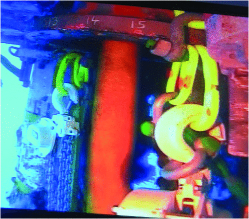
Heading control tugs (HCTs) and FPSO positioning
Two HCTs were used to keep the FPSO in the correct position and make changes to heading, when required, during riser and mooring chain disconnections (Fig. 29).

|
A fulltime towmaster on board the FPSO was responsible for maintaining and handling any changes to heading, keeping a close check on tow line tensions. For the final mooring chain cuttings, an additional standby vessel became available as a third HCT along with the other two. The configuration was changed to two tugs at the bow and one tug on the stern of the FPSO.
Routine heading changes, when required, were achieved in a reasonable time with estimated averages in ± 90 degrees changes in the region.
Substantial effort was made by the towmaster to hold the FPSO in a stable position for the final chain cut. Some tension was required on the final chain in order to allow deployment of the diamond wire saw and the chain ‘free falling’ onto the seabed.
HSE
The decommissioning team focused on the ‘safety first’ principle throughout all project phases. This attitude was displayed throughout the project by all parties and resulted in conducting all operations in a safe manner.
Comprehensive toolbox talks before execution of each operation also led to quite significant reduction in offshore duration, which led to an early sail-away of the FPSO without any recordable incident.
Overall the project was very successful, without any LTI or significant environmental incident.
Conclusions and lessons learned
Offshore interaction and chain of command between TechnipFMC and Eni was very effective and allowed the decision-making process to be on time, based on relevant and current information.
This campaign involved the first use of a GVIT. The successful use of this tool resulted in significant time and cost savings.
Primary and contingency methods of releasing the existing BSLMs did not give the expected results. However, contingencies like Broco cutting sped up the process in relation to flowline and umbilical disconnection.
Selection of VLS on the construction vessel proved to be a winning choice during recovery of the riser buoyancy modules and release of the flowlines onto the seabed in a controlled fashion.
The FPSO was successfully disconnected in 16 days compared with 22 planned days.
Conflicts of interest
No conflicts of interest exist for this project.
Acknowledgements
A special thanks to the Eni Australia Decommissioning Team, Kitan Joint Venture Partners, the TechnipFMC Project Team and ANPM (JPDA Regulator) who played a significant part in the overall success of this project.

Sashi Gajula has more than 14 years of professional experience in project management, offshore and onshore fabrication, offshore and onshore construction, and decommissioning projects. He started as a subsea engineer on construction vessels and was then later nominated to Senior/Lead project engineering roles. From 2012, he has been leading decommissioning projects in Eni Australia. Sashi holds a Bachelor’s in Mechanical Engineering from Osmania University, India, and a Master’s in Business Administration in Engineering Management from the University of Technology, Sydney Australia. He is also a Certified Project Manager from Stanford University. |

Bertrand Peuchot has more than twenty years of professional activities with management experience in pipe lay, fabrication and subsea construction activities. He started as a field engineer on construction vessels and was then nominated Deputy Project Manager with Stolt Offshore. He led the offshore department of a wind energy company named Eole-Res. He spent one year with Total in Gabon to coordinate the development of onshore and shallow water projects covering all disciplines. Bertrand then joined TechnipFMC and ran several major subsea and topside projects like CNOOC Panyu in China as a director of a consortium with COOEC and more recently Shell Prelude. Bertrand holds a Master’s Degree in Mechanical Engineering from Ecole Centrale de Lyon, France. |