Effects of the symmetry axis orientation of a TI overburden on seismic images
Chih-Hsiung Chang 1 3 Young-Fo Chang 2 Cheng-Wei Tseng 21 General Education Center, and Center of Energy Research and Sensor Technology – National Chiayi University, No. 300 Syuefu Road, Chiayi City 60004, Taiwan.
2 Institute of Seismology, National Chung Cheng University, No. 168, Sec. 1, University Road, Min-Hsiung Township, Chia-yi County 621, Taiwan.
3 Corresponding author. Email: charles@mail.ncyu.edu.tw
Exploration Geophysics 48(4) 449-455 https://doi.org/10.1071/EG15124
Submitted: 1 December 2015 Accepted: 11 May 2016 Published: 7 July 2016
Journal Compilation © ASEG Open Access CC BY-NC-ND
Abstract
In active tectonic regions, the primary formations are often tilted and subjected to the processes of folding and/or faulting. Dipping formations may be categorised as tilted transverse isotropy (TTI). While carrying out hydrocarbon exploration in areas of orogenic structures, mispositioning and defocusing effects in apparent reflections are often caused by the tilted transverse isotropy of the overburden. In this study, scaled physical modelling was carried out to demonstrate the behaviours of seismic wave propagation and imaging problems incurred by transverse isotropic (TI) overburdens that possess different orientations of the symmetry axis. To facilitate our objectives, zero-offset reflections were acquired from four stratum-fault models to image the same structures that were overlain by a TI (phenolite) slab. The symmetry axis of the TI slab was vertical, tilted or horizontal. In response to the symmetry axis orientations, spatial shifts and asymmetrical diffraction patterns in apparent reflections were observed in the acquired profiles. Given the different orientations of the symmetry axis, numerical manipulations showed that the imaged events could be well described by theoretical ray paths computed by the trial-and-error ray method and Fermat’s principle (TERF) method. In addition, outputs of image restoration show that the imaging problems, i.e. spatial shift in the apparent reflections, can be properly handled by the ray-based anisotropic 2D Kirchhoff time migration (RAKTM) method.
Key words: anisotropic migration, physical model, structure image, tilted transverse isotropy.
Introduction
In an undisturbed environment, the natural deposition process tends to produce horizontally layered sedimentary rock; such layered rock is categorised as vertical transverse isotropy (VTI) in seismic anisotropy. A VTI stratum possesses a vertical symmetry axis and exhibits physical properties that are independent of the azimuth. Subject to an orogenic process or uplift by salt, these horizontal strata can be thrust to the surface or folded so that they have inclined dip angles (Bally et al., 1966; Angelier et al., 1986; Huang et al., 2009). As a result of tectonic processes, the symmetry axis of once-horizontal stratification thus deviates from vertical. An inclined formation which has its symmetry axis tilted is often referred to as tilted transverse isotropy (TTI). In addition to VTI and TTI, in field mechanisms, stress-induced systematically parallel dipping fractures embedded in isotropic rock are referred to as horizontal transverse isotropic (HTI) (Angerer et al., 2002; Dewangan and Tsvankin, 2006a, 2006b). In short, the term TTI can be considered as a versatile model of TI because its symmetry axis does not need to be specifically oriented.
While carrying out petroleum exploration in the Alberta Rocky Mountain Foothills and the Gulf of Mexico, it has been found that the hydrocarbon reservoir is often overlain by imbricated thrust sheets or inclined strata which have been tilted by plate tectonics or upwardly migrating salt. These imbricated thrust sheets or inclined strata thus act as so-called TTI (Vestrum et al., 1999; Yan et al., 2004; Huang et al., 2009; Ursenbach and Bale, 2009). The existence of TTI causes lateral shifts in apparent reflections and leads to severe imaging problems. By means of both field and physical model studies, the mispositioning and defocusing effects caused by overburden TTI media have been observed by Isaac and Lawton (1999). Other studies have shown that the magnitude of imaging problems is dominated not only by the anisotropy itself and the inclination of dipping clastic sequences but also by changes in the offset of the source and receiver (Vestrum and Vermeulen, 2004; Holt, 2008). Hence, to obtain true images in areas of TTI, seismic data have to be properly processed by a reliable migration method.
Vestrum et al. (1999) and Grech et al. (2002) showed that the positioning and continuity of image structures below TTI strata can be improved, i.e. anisotropic images can be better focused, by anisotropic depth migration. Zhu et al. (2007) proposed a reformulated prestack Gaussian-beam depth migration (GBM) to restore the images of a step structure overlain by a TTI medium model and a dipping anisotropic thrust sheet. The algorithm of the modified prestack GBM was reformulated based on ray-tracing systems in terms of phase velocity. Combining this with prestack depth migration (PSDM), Behera and Tsvankin (2009) showed that the migration velocity analysis (MVA) algorithm (Sarkar and Tsvankin, 2004) can be efficiently used to image targets beneath TTI formations. When imaging mini-basins around salt bodies in Gulf of Mexico, Huang et al. (2009) showed that reverse time migration (RTM) could be applied to wide azimuth (WAZ) and multi-azimuth (MAZ) data to deal with large lateral velocity variation and a steeply dipping geological environment. The results of the reviewed studies indicate the imaging problems caused by TTI overburden can be handled by the technique of migration.
Though a suitable migration algorithm can be used to overcome the imaging problems encountered in structurally complex environments, a successful image restoration is highly dependent on the accuracy of the incorporated velocity model. Yan et al. (2004) proposed that a reliable anisotropy velocity model has to be built based on two of Thomsen’s parameters, ε and δ, strata dip θ, and a velocity (V0) normal to the bedding. Consequently, the accuracy of these anisotropic elements, i.e. ε, δ, θ and V0, is vitally important in building anisotropy velocity models. In field operations, these elements are often obtained by wide azimuth non-hyperbolic moveout (Alkhalifah and Tsvankin, 1995; Grechka and Tsvankin, 1998), walkway or multioffset vertical seismic profile (VSP) (Armstrong et al., 1995; Leslie and Lawton, 1999; Newrick et al., 2000) and sonic log (Grech et al., 2001; Sinha, 2011).
In fact, when seismic imaging is carried out in an area of fold-and-thrust belts or subsalt, poor data quality is inevitable due to complex wave fields and low signal-to-noise (S/N) ratios. Hence, to understand and develop new processing techniques in an area of complicated structure, forward modelling studies could be considered as the most powerful tool. To highlight and demonstrate the image problems caused by the symmetry axis orientation of a TTI overburden, four stratum-fault physical models were created. The symmetry axes of the TTI overburdens were vertical, tilted and horizontal. The structure was then ultrasonically scanned to demonstrate sensitivity of the apparent reflections and diffraction patterns in response to the orientation of the symmetry axis of an overburden TI layer.
Laboratory manipulation
The physical models
Phenolite made of interlaced resin and paper or woven fibre is a popular anisotropic material in studies of elastic wave propagation (Chang et al., 1994; Okoye et al., 1995; Waluyo et al., 1995; Grechka and Tsvankin, 1999; Mah and Schmitt, 2003). Prior to our laboratory manipulation, the characteristics of the phenolite used for modelling were tested as a TI material. The five elastic constants of the phenolitic block, normalised by density (1.57 × 10³ kg/m3), were measured as C11 = 16.49, C13 = 6.15, C33 = 8.57, C44 = 2.01 and C66 = 4.32 (× 106 m2/s2). After converting the measured elastic constants, the three Thomsen’s non-dimensional anisotropic parameters turned out to be ε = 0.46, γ = 0.57 and δ = 0.21.
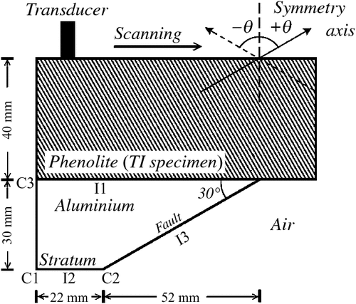
In the laboratory, four two-layer (stratum-fault) physical models were built to simulate the dipping clastic sequences often encountered in the areas of fold-thrust belts. The upper layer of the two-layer model was built of a TI overburden layer (phenolite), and the bottom was an isotropic layer (aluminium wedge). Therefore, the scaled model could be treated as a fault structure overlain by a TI overburden. The longitudinal (P) wave velocity of the aluminium block was 6400 m/s, and the dip angle of the fault plane was 30°. All four scale models were the same in dimensions and geometries except for the orientation of the symmetry axis of the overburden TI slab. The symmetry axes of the TI slabs were vertical (θ = 0°), tilted (θ = ± 60°) or horizontal (θ = 90°). θ was the angular deviation of the symmetry axis of the TI slab from the vertical, and positive θ was measured clockwise. A TI slab with a symmetry axis θ = –60° could be achieved by turning a TI slab with a tilted symmetry axis (θ = 60°) upside down. Figure 1 shows a schematic diagram of the stratum-fault models and the arrangement of data acquisition.
|
Reflection experiments
Our laboratory manipulations were completed at the Ultrasonic Physical Modelling Laboratory, National Chung Cheng University, Taiwan. A longitudinal mode P-type transducer (PANAMETRICS A133S, 2.25 MHz, 6 mm) served as a transceiver. A PANAMETRICS 5058 pulser-receiver in single probe pulse/echo mode was adopted to excite the active transducer, and synchronise (SYN) the digital oscilloscope. The retrieved analogue electrical signals were amplified, filtered and then sent to a TEKTRONIX TDS-5032B oscilloscope to be digitised, and stacked 100 times to increase the S/N ratio. The digitised radio-frequency (RF) signal was then downloaded from the digital oscilloscope via a general purpose interface bus (GPIB) and IEEE-488 communication to the PC for further processing. Once the ultrasonic signal was retrieved, the transducer was manually moved to the next location. The spatial interval of the successive measurement was 1 mm. Because only a single transducer was used to serve as source and receiver, the acquired profiles can be considered as zero-offset reflections. In all, four reflection profiles were collected. Each profile consisted of 50 traces, and each trace consisted of 5000 points sampled at 8 ns, i.e. 40 μs in recorded length.
Numerical manipulations
In the numerical manipulations, the theoretical arrival times and ray paths of the apparent reflections were calculated using the trial-and-error ray method and Fermat’s principle (TERF) (Uren et al., 1991; Chang and Kuo, 2005; Sun et al., 2012) and ray-based anisotropic 2D Kirchhoff time migration (RAKTM), a great circle method (Dobrin and Savit, 1988; Yilmaz, 1987). The associated group velocity of the calculated ray paths of the P-wave in the TI stratum was obtained from the known elastic coefficients and orientation of the symmetry axis of the TI stratum. The potential transmission (or reflection) positions of the P-wave on the interface of phenolitic slab and aluminium (I1 in Figure 1) were calculated with a 0.1 mm incremental interval for the reflection which could be detected at that transceiver position. Following the principle of least time, the pertinent ray paths of the P-wave from the source to the transmission position in the TI stratum and the transmission position to the reflector (or diffractor) in the isotropic aluminium wedge were obtained. In other words, the theoretical ray path and the relative travel times of the propagating P-wave in the TI stratum and the isotropic aluminium wedge were determined. The theoretical ray path at each transceiver position was computed and displayed adjacently to explore the origin of the relative reflections and identify the imaged events.
Because we intended to demonstrate the spatial misposition of reflections caused by the dipping symmetry axis of a TI overburden, the RAKTM method was applied only to apparent reflections whose arrival times were detected later than those that originated from interface I1. Basically, this is the scheme of Kirchhoff time migration based on the semicircle superposition. According to the idea of impulse response, a seismic section can be considered to consist of a series of spikes, i.e. reactions of point reflectors. The possible positions of the reflector (or diffractor) in the aluminium wedge are located on a semicircle with the relative virtual source as its centre. Therefore, the transmission points of theoretical ray paths distributed on interface I1, as computed from the relative transceiver position, served as the virtual sources. In the process of RAKTM, the recorded amplitude of the ultrasound was redistributed and projected onto a semicircle on the output migrated time section. Theoretically, ‘noises’ are cancelled out by destructive interference, and migrated reflectors occur where the semicircles constructively interfere as a result of superposition of the many semicircles in the migrated profile.
Results
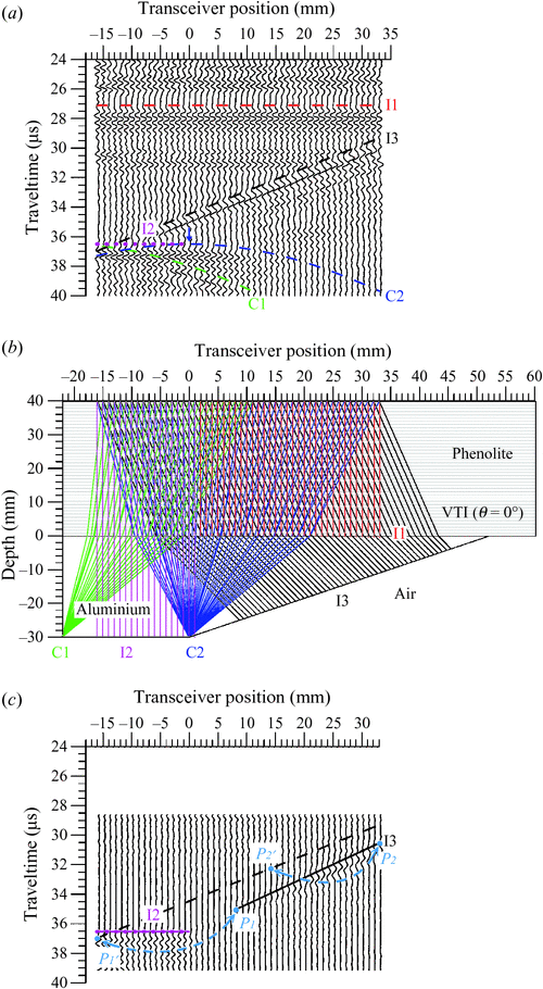
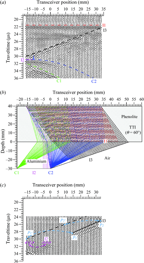
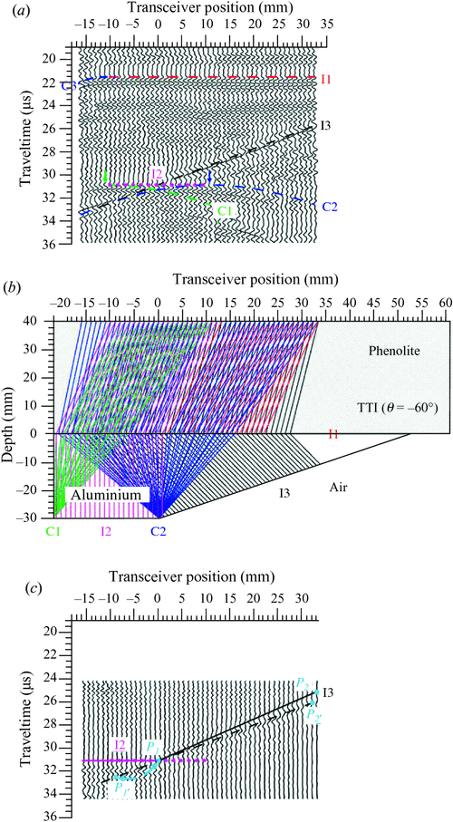
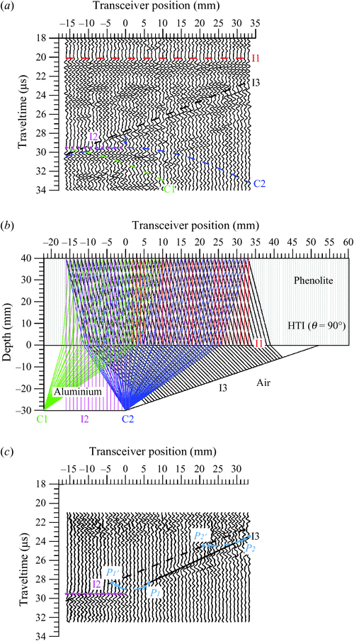
Reflection profiles acquired from the four TI stratum-fault models are shown in Figures 2a, 3a, 4a and 5a, where the symmetry axes of the overlain TI strata are tilted by 0°, –60°, 60° and 90°, respectively. In these figures, the red dashed lines, magenta short dashed lines and black dashed lines are the theoretical arrival times of reflected P-waves originating from interfaces I1, I2 and I3. In addition, the green dashed lines, blue dashed lines and deep blue dashed lines (in Figure 4a) are the theoretical arrival times of diffracted P-waves originating from the C1 and C2 corners and the C3 terminal. The transceiver position at 0 mm is located directly above the corner C2. The blue and green arrows are used to mark the apices of the diffraction patterns of C1 and C2. In the following sections of this paper, the corresponding ultrasonic echoes reflected from the I1, I2 and I3 interfaces and diffracted from C1, C2 and C3 are called I1, I2, I3, C1, C2 and C3 events. The theoretical ray paths of the original reflections and the arrivals of the events I1, I2, I3, C1, C2 and C3 were calculated by the TERF method using the group velocities of the propagating P-waves (Figures 2b, 3b, 4b and 5b). The meanings of the colours of the ray paths, shown in Figures 2b, 3b, 4b and 5b, are the same as those used in Figures 2a, 3a, 4a and 5a. The computed ray paths thus provide an easy way to trace where the apparent reflections come from. Once the target reflectors and diffractors were identified in the acquired profiles, the RAKTM method was applied to the apparent reflections to restore the true images. In the zero-offset profiles, it was apparent that most downgoing energy was reflected from interface I1, and this fact resulted in the weakening of the reflection amplitudes originating from the bottom (I2) and fault plane (I3). Hence, to facilitate and enhance the quality of migration, the RAKTM method was only applied to reflections detected later than I1 reflections. The results of anisotropic migration are shown in Figures 2c, 3c, 4c and 5c. In these figures, the short dashed magenta lines and black dashed lines are the same as those used in Figures 2a, 3a, 4a and 5a. The magenta and black lines represent the true positions of the interfaces I2 and I3 in the migrated section, respectively. More details of the results are addressed as follows.
|
|
|
|
Stratum-fault model I: VTI (θ = 0°) overburden
In the case of Model I, the symmetry axis of the TI overburden was vertically oriented. Figure 2a is the profile of reflections acquired from Model I. Events I1 and I2 were observed at 27.0 μs and 36.5 μs, respectively. From right to left, the theoretical arrival times of the fault plane (I3) events were diagonally detected at 29.3 μs and 37 μs in the profile. The apparent slope of the fault plane was measured as –0.156 μs/mm or 26.5° in dip angle. Due to insufficient coverage of transceiver positions, only part of the C1 diffraction pattern was observed. However, a symmetrical diffraction pattern which originated from the corner C2 was delineated, with its apex positioned right below the transceiver position at 0 mm. According to the theoretical ray paths and arrivals shown in Figure 2b, events of reflections and diffraction patterns shown in Figure 2a were described.
Because reflections originating from interface I1 were detected at 27.0 μs, the RAKTM method was applied to the time gate of 28.5 μs to 40.0 μs. It can be seen that the I2 event remained at the position where it was originally detected (Figure 2a) because the propagations of P-waves were reflected back perpendicularly from interface I2. Therefore, the short dashed magenta line and solid magenta line overlapped in the migrated profile. The apparent fault plane, i.e. segment P1ʹP2ʹ was migrated to segment P1P2, i.e. the solid black line. The dip angle of the migrated segment P1P2 is 30°; in other words, the true fault plane was successfully restored. It can also be seen that nothing was obtained between the right terminal of I2 and P1 of segment P1P2, which is the lower part of the fault plane I3, due to the limitation of the coverage of transceiver positions and because no reflections from this part were detected in the acquired profile (Figure 2a). In addition, I3 reflections received at the right upper part of the black dashed line (above point P2ʹ) migrated away and were no longer shown in the migrated profile. C1, which was reconstructed, is not shown in the migrated profile. This is because the restored C1 was positioned outside the profile. However, the diffracted energy originating from C2 was well reconstructed and repositioned at the right terminal of I2.
Stratum-fault model II: TTI (θ = 60°) overburden
In the case of Model II, the symmetry axis of the TI overburden was tilted by 60°. Figure 3a shows the profile of reflections acquired from Model II. The arrivals of I1 and I2 events were, respectively, observed at 21.5 μs and 31.0 μs, earlier than those imaged in Figure 2a. The direction of the ‘tilt’ in the symmetry axis of the TI stratum made the image of I2 shift leftward, and it could only be detected when the transceivers were positioned in a range of –12 mm to –16 mm. In addition, apparent reflections originating from the C1 corner and C2 joint were also shifted leftward and delineated as two asymmetrical diffraction patterns. The apex of the C2 diffraction pattern was positioned right below the transceiver position –11 mm (blue arrow). From upper right to the lower left, the fault plane was imaged at 22.3 μs and 30.0 μs in the acquired profile. The slope of the imaged fault plane was measured as –0.156 μs/mm or 26.5° in dip angle, which was the same as what we observed in Figure 2a. The identifications of the imaged events were confirmed by the theoretical ray paths and arrivals that were computed by TERF and shown in Figure 3b.
In the process of image restoration, the RAKTM method was applied to the time gate of 24 μs to 35 μs. Figure 3c shows the output of RAKTM. In Figure 3c, I2, I3 and C2 were successfully restored and repositioned to their true positions. Some of the I3 reflections were received beyond the right upper part of the apparent fault plane, i.e. P2ʹ on the black dashed line, and the reflections from the C1 corner migrated away and were no longer shown in the migrated profile.
Stratum-fault model III: TTI (θ = –60°) overburden
In the case of Model III, the symmetry axis of the TI overburden was tilted counterclockwise by 60°, i.e. θ = –60°. Figure 4a shows the profile of reflections acquired from Model III.
In the profile, the events of I1 and I2 were imaged at the same arrival times, i.e. 21.5 μs and 31.0 μs, as those imaged and shown in Figure 3a. However, event I2 was a stretched image and could be detected from transceiver positions –10 mm to 12 mm. The upper right and the lower left terminals of I3 were imaged at 25.8 μs and 33.4 μs. It is interesting to note that the slope of the measured apparent fault plane was same as what was imaged in the previous case (Figure 3a). Reflections originating from corner C1 and joint C2 showed up as two asymmetrical diffraction patterns and their apices were imaged right below the transceiver positions –11 mm (indicated by a green arrow) and 11 mm (indicated by a blue arrow). Compared with the images in Figure 2a, events I2, C1 and C2 were shifted rightward significantly. Due to the lateral shifts, reflections originating from C3, which were not observed in Figures 2a and 3a, were detected. In the upper left side of Figure 4a, the deep blue semi-diffraction pattern was delineated from the apparent reflections originating from C3. The theoretical ray paths and arrivals shown in Figure 4b thus can be used to assist in identifying the origins of the events that were imaged in Figure 4a.
In a process similar to what was done in Figure 3, RAKTM was applied to the time gate of 24 μs to 35 μs. Figure 4c shows the output of RAKTM. In Figure 4c, the I2 event (short-dashed magenta line), which had been a stretched image, was well migrated. The true fault plane (P1P2, black line) was also repositioned from the imaged one (P1ʹP2ʹ, black dashed line). C2 was restored and positioned at the joint of the magenta line (I2) and black line (I3). In other words, the interfaces I2 and I3, and the joint C2 were all satisfactorily reconstructed. However, the migrated C1 and C3 events were positioned outside and no longer showed up in the migrated section (Figure 4c).
Stratum-fault model IV: HTI (θ = 90°) overburden
In the case of Model IV, the symmetry axis of the TI overburden was horizontally oriented. Figure 5a is the profile of reflections acquired from Model IV. In Figure 5a, it can be seen that events I1 and I2 were imaged earlier than those imaged in the previous profiles (Figures 2a, 3a and 4a) and were observed at 20.0 μs and 29.5 μs, respectively. This happened because a seismic wave travels with the highest velocity in the layering direction of a TI material. The elastic energy emitted from the transceivers was propagated directly downward and upward, reflecting from the interfaces I1 and I2 with the shortest travel time. The upper right and the lower left terminals of fault plane I3 were imaged at 22.6 μs and 30.3 μs, and the slope of the apparent fault plane image was –0.156 μs/mm. Due to the properties of symmetry, the reflections originating from corner C1 and joint C2 were delineated as two symmetrical diffraction patterns. All of the imaged events can be directly inferred and identified from the theoretical ray paths shown in Figure 5b.
In this case of an HTI overburden, RAKTM was applied to the time gate of 21 μs to 33 μs in the process of image restoration. Figure 5c shows the results of migration. Once again, reflections originating from interface I2 remained in the positions where they were observed. This occurred because the ray paths of the apparent reflections were all parallel to each other and normal to the top and bottom surfaces (Figure 5b). However, only part of the true fault plane (I3) was reconstructed, i.e. segment P1P2 (black solid line). Energy diffracted from joint C2 was also satisfactorily restored. Due to insufficient coverage of reflections (Figure 5b), nothing was restored in between joint C2 and the lower terminal (P1) of the restored fault plane. Energy diffracted from corner C1 was migrated outside in this migrated profile.
Discussion
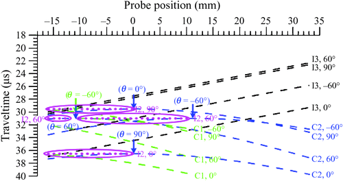
In this study, four TI stratum-fault models were created to explore the image problems that could be encountered when imaging substructures overlain by a TI formation. The symmetry axes of the TI formations of the models were vertical (θ = 0°), tilted (θ = ±60°) and horizontal (θ = 90°). Four zero-offset reflection profiles were acquired on the free surfaces of the TI strata. In Figure 6, events of I2, I3, C1 and C2 that were imaged in Figures 2a, 3a, 4a and 5a are displayed together.
|
In a TI medium, P-waves travel with the lowest velocity parallel to the symmetry axis and the highest velocity in the direction transverse to the symmetry axis. Therefore, the images of I2, I3, C1 and C2 shown in Figure 6 were detected earlier when the symmetry axis of the upper TI stratum of the created model was horizontally oriented (θ = 90°), and the images were observed later when the symmetry axis of the upper TI stratum of the created model was vertically oriented (θ = 0°). In addition, reflections originating from corner C1 and joint C2 showed up as two symmetrical diffractions with apices positioned right below the transceiver position, 0 mm, in both VTI (θ = 0°) and HTI (θ = 90°). In cases of TTI overburden (θ = ±60°), the interface I2 was imaged at the same arrival times. Subjected to the ‘tilted’ symmetry axis, the images of the target structures were shifted significantly leftward when the symmetry axis was tilted by 60° and shifted rightward when the symmetry axis was tilted by –60°. The phenomena of shifted images can be inferred from the theoretical ray paths (Figures 2b, 3b, 4b and 5b). A more interesting observation is that instead of symmetric diffraction patterns, reflections originating from corner C1 and joint C2 were delineated as two asymmetrical ones in the models of TTI overburden.
Regardless of the orientation of the symmetry axis of the model, the P-waves travelled with the same propagating times in the aluminium wedge. This is because the in-out ray paths were all perpendicular to the I2 interface. Converted to depth, the thickness of the substratum turned out to be 3.0 cm, which was the true thickness of the aluminium wedge. Although the apparent reflections of fault plane I3 were imaged in different spatial positions and at different arrival times, the apparent fault planes possessed the same slope, i.e. –0.156 μs/mm. The theoretical ray paths shown in Figures 2b, 3b, 4b and 5b provide an explanation for the equal slopes in the imaged fault planes. Slopes were equal because the ray paths of the reflections originating from the fault plane were parallel to each other and normal to the fault plane I3 in the aluminium wedge. The time differences and the spatial mispositions in the imaged fault planes were simply induced by the orientation of the symmetry axis of the TI stratum in the overburden.
In combination, the anisotropy and the orientation of the symmetry axis, as well as the thickness of the overburden TI stratum, affect the images in surface seismic data. Making use of laboratory manipulation, the elastic constants of the modelling material can be measured in advance. Therefore, the theoretical ray paths of the imaged events can be computed by TERF. Once the velocity model, built from the pre-measured elastic constants, was incorporated into RAKTM, our results showed that all of the imaged events were successfully repositioned, i.e. the true geometry of the image was satisfactorily restored. The results of RAKTM thus stress that an accurate velocity model is the most important factor in a successful method of seismic migration.
Conclusions
In this study, we explored the influence of symmetry axis orientation of a TI overburden on seismic imaging using our scaled laboratory experiments. Although the physical models created in this study were relatively simple, the spatial mispositioning of reflections in response to the symmetry axis orientation of the TI overburden were clearly demonstrated. In the cases of VTI and HTI overburdens, reflections arising from a plane reflector were simply shifted downward or upward. In addition, a symmetric diffraction pattern of reflections, originating from the diffractor, was observed. Once the symmetry axis of the TI overburden was tilted, neither vertically nor horizontally oriented, reflections arising from the plane reflector were shifted laterally. Hence, the effects of ‘tilted’ overburden were revealed by the asymmetrical diffraction pattern of reflections coming from the discontinuity. Although the created fault planes were imaged at different arrival times and the actual dip (30°) was not accurately imaged, the apparent faults possessed same dip (26.5°) in all of the four acquired profiles. In other words, the apparent dip of an inclined plane reflector was dominated by the anisotropy of the TI overburden but by not the orientation of the symmetry axis. Taking advantage of modelling studies, reliable velocity models can be built using the previously measured elastic constants. When reliable velocity models were incorporated into the numerical manipulations, theoretical ray traces showed that the origins of reflections can be properly positioned by the TERF method; therefore, the apparent images in the acquired profiles can be delineated with confidence. To address the image problems caused by the TI overburden, laboratory data were processed by RAKTM. The migrated profiles satisfactorily showed that the apparent reflections were all repositioned to where they originated. Benefiting from the forward modelling studies, the phenomenon of spatial mispositioning in apparent reflections caused by the symmetry axis orientation of the TI overburden was observed. The results of numerical processes, i.e. the TERF and RAKTM methods, corroborate that a reliable velocity model is vital to the success of reflection seismology in an area of complex structures.
Acknowledgements
We express our appreciation to Dr Mamoru Takanashi and another anonymous reviewer for providing very constructive suggestions and comments in revising this paper. The research leading to this paper was financially supported by the National Science Council under grant no. MOST 103–2116-M-194–011- and MOST 104–2116-M-415–002-.
References
Alkhalifah, T., and Tsvankin, I., 1995, Velocity analysis in transversely isotropic media: Geophysics, 60, 1550–1566| Velocity analysis in transversely isotropic media:Crossref | GoogleScholarGoogle Scholar |
Angelier, J., Barrier, E., and Chu, H. T., 1986, Plate collision and paleostress trajectories in a fold-thrust belt: the foothills of Taiwan: Tectonophysics, 125, 161–178
| Plate collision and paleostress trajectories in a fold-thrust belt: the foothills of Taiwan:Crossref | GoogleScholarGoogle Scholar |
Angerer, E., Horne, S. A., Gaiser, J. E., Walters, R., Bagala, S., and Vetri, L., 2002, Characterization of dipping fractures using PS modeconverted data: 72nd Annual International Meeting, SEG, Expanded Abstracts, 1010–1013.
Armstrong, P. N., Chmela, W., and Leaney, W. S., 1995, AVO calibration using borehole data: First Break, 13, 319–328
| AVO calibration using borehole data:Crossref | GoogleScholarGoogle Scholar |
Bally, A. W., Gordy, P. L., and Steward, G. A., 1966, Structure, seismic data, and orogenic evolution of southern Canadian Rocky mountains: Bulletin of Canadian Petroleum Geology, 14, 337–381
Behera, L., and Tsvankin, I., 2009, Migration velocity analysis for tilted TI media: Geophysical Prospecting, 57, 13–26
| Migration velocity analysis for tilted TI media:Crossref | GoogleScholarGoogle Scholar |
Chang, Y. F., and Kuo, Y. T., 2005, Travel times and reflection points for reflected P-waves in transversely isotropic media: Terrestrial, Atmospheric and Oceanic Sciences, 16, 1061–1077
Chang, C. H., Gardner, G. H. F., and McDonald, J. A., 1994, A physical model study of shear-wave propagation in a transversely isotropic solid: Geophysics, 59, 484–487
| A physical model study of shear-wave propagation in a transversely isotropic solid:Crossref | GoogleScholarGoogle Scholar |
Dewangan, P., and Tsvankin, I., 2006a, Modeling and inversion of PS wave moveout asymmetry for tilted TI media: Part 1 – Horizontal TTI layer: Geophysics, 71, D107–D121
| Modeling and inversion of PS wave moveout asymmetry for tilted TI media: Part 1 – Horizontal TTI layer:Crossref | GoogleScholarGoogle Scholar |
Dewangan, P., and Tsvankin, I., 2006b, Modeling and inversion of PS wave moveout asymmetry for tilted TI media: Part 2 – Dipping TTI layer: Geophysics, 71, D123–D134
| Modeling and inversion of PS wave moveout asymmetry for tilted TI media: Part 2 – Dipping TTI layer:Crossref | GoogleScholarGoogle Scholar |
Dobrin, M. B., and Savit, C. H., 1988, Introduction to geophysical prospecting (4th edition): McGraw-Hill.
Grech, M. G. K., Cheadle, S., Don, C., and Lawton, D. C., 2001, Integrating borehole information and surface seismic for velocity anisotropy analysis and depth imaging: The Leading Edge, 20, 519–523
| Integrating borehole information and surface seismic for velocity anisotropy analysis and depth imaging:Crossref | GoogleScholarGoogle Scholar |
Grech, M. G. K., Don, C., Lawton, D. C., and Gray, S. H., 2002, A multioffset vertical seismic profiling experiment for anisotropy analysis and depth imaging: Geophysics, 67, 348–354
| A multioffset vertical seismic profiling experiment for anisotropy analysis and depth imaging:Crossref | GoogleScholarGoogle Scholar |
Grechka, V., and Tsvankin, I., 1998, Feasibility of nonhyperbolic moveout inversion in transversely isotropic media: Geophysics, 63, 957–969
| Feasibility of nonhyperbolic moveout inversion in transversely isotropic media:Crossref | GoogleScholarGoogle Scholar |
Grechka, V., and Tsvankin, I., 1999, 3-D moveout velocity analysis and parameter estimation for orthorhombic media: Geophysics, 64, 820–837
| 3-D moveout velocity analysis and parameter estimation for orthorhombic media:Crossref | GoogleScholarGoogle Scholar |
Holt, R., 2008, Estimating lateral positioning uncertainty after anisotropic depth migration: a thrust belt case history: 78th Annual International Meeting, SEG, Expanded Abstracts, 232–236.
Huang, T., Zhang, Y., and Zhang, H., 2009, The benefit of TTI reverse time migration for subsalt imaging, Gulf of Mexico: 71st EAGE Conference and Exhibition, 8–11.
Isaac, J. H., and Lawton, D. C., 1999, Image mispositioning due to dipping TI media: a physical seismic modeling study: Geophysics, 64, 1230–1238
| Image mispositioning due to dipping TI media: a physical seismic modeling study:Crossref | GoogleScholarGoogle Scholar |
Leslie, J. M., and Lawton, D. C., 1999, Determination of anisotropic parameters, in situ, using a multioffset vertical seismic profile: 69th Annual International Meeting, SEG, Expanded Abstracts, 1267–1270.
Mah, M., and Schmitt, D. R., 2003, Determination of the complete elastic stiffnesses from ultrasonic phase velocity measurements: Journal of Geophysical Research, 108, ECV 6-1–ECV 6-11
| Determination of the complete elastic stiffnesses from ultrasonic phase velocity measurements:Crossref | GoogleScholarGoogle Scholar |
Newrick, T. R., Lawton, D. C., Deborah, A., and Spratt, D. A., 2000, Multi-offset VSP traveltime inversion for anisotropy analysis: 70th Annual International Meeting, SEG, Expanded Abstracts, 2237–2240.
Okoye, P. N., Uren, N. F., McDonald, J. A., and Ebrom, D. A., 1995, The dependence of lateral resolution on the orientation of symmetry axis and elastic parameter in transversely isotropic media: 65th Annual International Meeting, SEG, Expanded Abstracts, 567–571.
Sarkar, D., and Tsvankin, I., 2004, Migration velocity analysis in factorized VTI media: Geophysics, 69, 708–718
| Migration velocity analysis in factorized VTI media:Crossref | GoogleScholarGoogle Scholar |
Sinha, B. K., 2011, Estimation of rock anisotropic constants using sonic data from deviated wellbores: Ultrasonics Symposium (IUS), 2011 IEEE International, 2061–2064.
Sun, L. C., Chang, Y. F., Chang, C. H., and Chung, C. L., 2012, A physical modeling studying the travel times and reflection points of SH-waves reflected from transversely isotropic media with a tilted symmetry axis: Exploration Geophysics, 43, 149–155
| A physical modeling studying the travel times and reflection points of SH-waves reflected from transversely isotropic media with a tilted symmetry axis:Crossref | GoogleScholarGoogle Scholar |
Uren, N. F., Gardner, G. H. F., and McDonald, J. A., 1991, Anisotropic wave propagation and zero-offset migration: Exploration Geophysics, 22, 405–410
| Anisotropic wave propagation and zero-offset migration:Crossref | GoogleScholarGoogle Scholar |
Ursenbach, C., and Bale, R. A., 2009, TTI wave-equation migration for Canadian Foothills depth imaging: The Leading Edge, 28, 1344–1351
| TTI wave-equation migration for Canadian Foothills depth imaging:Crossref | GoogleScholarGoogle Scholar |
Vestrum, R., and Vermeulen, P., 2004, Sideslip and smear beneath dipping transversely isotropic strata: 74th Annual International Meeting, SEG, Expanded Abstracts, 175–178.
Vestrum, R. W., Lawton, D. C., and Schmid, R., 1999, Imaging structures below dipping TI media: Geophysics, 64, 1239–1246
| Imaging structures below dipping TI media:Crossref | GoogleScholarGoogle Scholar |
Waluyo, W., Uren, N. F., and McDonald, J. A., 1995, Poisson’s ratio in transversely isotropic media and its effects on amplitude response: an investigation through physical modelling experiments: 65th Annual International Meeting, SEG, Expanded Abstracts, 585–588.
Yan, L., Lines, L. R., and Lawton, D. C., 2004, Influence of seismic anisotropy on prestack depth migration: The Leading Edge, 23, 30–36
| Influence of seismic anisotropy on prestack depth migration:Crossref | GoogleScholarGoogle Scholar |
Yilmaz, O., 1987, Seismic data processing: Society of Exploration Geophysicists.
Zhu, T., Gray, S. H., and Wang, D., 2007, Prestack Gaussian-beam depth migration in anisotropic media: Geophysics, 72, S133–S138
| Prestack Gaussian-beam depth migration in anisotropic media:Crossref | GoogleScholarGoogle Scholar |

