

Arid erosion mapping: comparing LiDAR and structure from motion
Angus Retallack A * , Dillon Campbell B , Graeme Finlayson A C , Ramesh Raja Segaran D , Bertram Ostendorf A , Molly Hennekam B , Sami Rifai A and Megan Lewis A
A
B
C
D
Abstract
Rapid development and uptake in uncrewed aerial vehicles (UAVs) for environmental monitoring, specifically using three-dimensional data from LiDAR and structure from motion (SfM), has enabled improved condition assessment, including fine-scale erosion monitoring. Comparing the precision of LiDAR and SfM for measuring erosion is essential in enabling appropriate method selection. Additionally, knowledge regarding optimal flight heights allows for consideration of the trade-off among survey areas, flight times and precision. We assessed UAV-based LiDAR and SfM for providing high-precision digital surface models (DSM) of substantial gully erosion on a conservation reserve in the southern Australian arid rangelands. The gullies exist in low-slope chenopod shrublands with calcareous soils, and are of significant management concern, with erosion occurring rapidly over short periods following irregular and intense rainfall events. Root mean squared error (RMSE) values for SfM-derived DSMs with resolutions of 2, 4 and 6 cm were lower than comparable LiDAR datasets (SfM = 0.72–1.39 cm; LiDAR = 2.08–3.15 cm). Additionally, 2 cm SfM-derived datasets exhibit notably lower RMSE values than 4 and 6 cm datasets (2 cm = 0.72 cm; 4–6 cm = 2.08–3.15 cm). Change detection over the 1-year study period highlighted erosion in locations of management concern. We propose that, although both methods are of value, SfM is preferred over LiDAR because of its simplicity, reduced cost, and the additional monitoring capabilities of visible-colour imagery, with no notable sacrifice in precision. Visible-colour survey areas and times can be optimised by increasing flight height without dramatic losses in precision. The use of either method will be of great benefit for the monitoring of arid gully erosion and assessing the effectiveness of management interventions, allowing adaptive management and leading to improved condition of arid rangelands into the future.
Keywords: arid rangelands, digital elevation model (DEM), gully erosion, LiDAR, rangeland management, remote sensing, soil erosion, Structure from motion, UAV.
Introduction
Arid and semi-arid rangelands comprise a large proportion of the Earth’s surface, and provide resources essential for the survival of billions of people (UN EMG 2011). However, climate change and anthropogenic land use have caused significant degradation, of which soil erosion is a major component. Erosion is exacerbated by reduced vegetation cover owing to long-term overgrazing (Jones 2000), the construction of vehicle tracks and other infrastructure, as well as increased rainfall irregularity leading to more highly concentrated rainfall events (Molnar 2001; Elaloui et al. 2023).
Monitoring is essential in understanding erosion and informing effective management. Approaches range from on-ground measurements of sediment movement by wind or water (Breshears et al. 2003; Desir and Marín 2007; Khalili Moghadam et al. 2015; Jeanneau et al. 2019), to remote sensing-based methods at a variety of scales (Fadul et al. 1999; Vrieling 2006; Koci et al. 2017). Because of the extensive and inaccessible nature of many arid regions, on-ground approaches are generally not financially and physically feasible for repeated measurements. Remote sensing addresses this issue, enabling objective, regular, repeatable and accurate measurements of various landscape-condition indicators (Booth and Tueller 2003), including erosion. Airborne and satellite-based methods have been used over several decades for monitoring erosion at broad spatial scales (Dwivedi et al. 1997; Fadul et al. 1999; Martínez-Casasnovas et al. 2003; Vrieling 2006; Vrieling et al. 2007; Gillan et al. 2016), but are cost prohibitive to operate in remote areas at the required resolution to measure fine-scale erosion (i.e. <10 cm). Following recent rapid development of sensor and platform technologies, approaches using LiDAR (Johansen et al. 2012; Koci et al. 2017) and structure from motion (SfM) photogrammetry (D’Oleire-Oltmanns et al. 2012; Gómez Gutiérrez et al. 2018; Alfonso-Torreño et al. 2021; Guan et al. 2021) have seen significant use and stand out as favourable methods for mapping fine-scale erosion features (Chakrabortty and Pal 2023; Retallack et al. 2023). However, examples often focus on agricultural and high-slope areas (Perroy et al. 2010; Yang et al. 2019; Hout et al. 2020; Alexiou et al. 2021; Guan et al. 2021), with limited use of these technologies for mapping low-lying arid erosion gullies at high spatial resolutions (Johansen et al. 2012; Koci et al. 2017; Gómez Gutiérrez et al. 2018; Alfonso-Torreño et al. 2021; Anderson et al. 2023).
Although convention suggests that LiDAR is the superior of the two approaches, its cost and complexity of data collection make it less favourable than SfM. Additionally, owing to greatly increased interest in visible-colour uncrewed aerial vehicles (UAVs) over recent years, many landholders and management groups are already in possession of these imaging platforms. Furthermore, SfM data collection requires less training and experience than a LiDAR-based protocol. However, a comparison of the precisions of both methods is required to determine whether the SfM method is feasible for precise monitoring. Of studies conducted in low-slope arid environments, a direct comparison between the two methods is yet to be made, as is a comparison between SfM-derived digital surface-model (DSM) resolutions. Focus on this landscape type is important because the low slopes and lack of sparse vegetation cover compared with other study areas greatly affects the measurement accuracy that may be expected. because these comparisons are important in evaluating the precision of LiDAR- and SfM-based DSMs, and their potential for long-term change detection, this study sought to address the following tasks:
method precision: we assessed the precision of both LiDAR and SfM-derived DSMs;
method comparison: we compared precisions for LiDAR and SfM-derived DSMs of the same terrain, with the goal of evaluating the potential for consumer-level UAVs to generate high-precision elevation models using SfM;
SfM resolution comparison: we compared SfM-derived DSMs with three different ground sampling distances (GSD), driven by the desire to maintain high precision while optimising survey area and survey time; and
change detection: we assessed change at a prominent erosion feature using SfM-derived DSMs collected 1 year apart.
Materials and methods
Study context and site
The study was conducted at Boolcoomatta Station Reserve, a 63 000 ha former sheep station located in the southern Australian rangelands (Fig. 1). The property has a mean annual rainfall (1982–2010) of 207 mm (Bureau of Meteorology 2010). The reserve, managed for conservation since 2006 by Bush Heritage Australia, comprises chenopod shrublands (Bastin and ACRIS Management Committee 2008) with localised communities of river red gum, mulga woodlands and ephemeral wetlands (Bush Heritage Australia 2019). The western end of the property, where our study sites are situated, is characterised by gentle slopes near the low-lying Olary Ranges, with calcarosol soils (Searle 2021; Soil Science Australia 2023).
Boolcoomatta Station Reserve is located ~380 km north-east of Adelaide in the southern arid rangelands. The erosion sites that are the focus of this study are situated at the western boundary of the property, adjacent to neighbouring Bimbowrie Conservation Park.
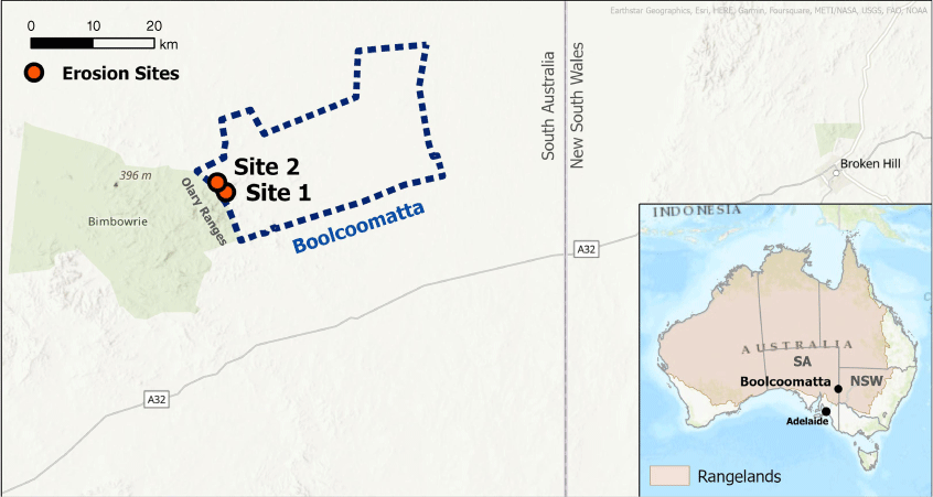
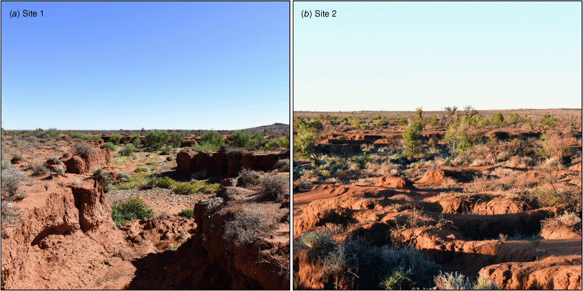
Over 150 years, sheep grazing and the associated vegetation changes increased erosion and erosion risk across the property, particularly where water flows from the Olary Ranges to the west. This study focused on two sites of erosion caused by these flows. Site 1 is characterised by a single erosion gully up to 2 m deep (Fig. 2a; 140.4185°E, 31.9863°S). Site 2, further downstream, is more shallow and widespread, with multiple water courses traversing the affected area (Fig. 2b; 140.4047°E, 31.9724°S). Vegetation at both sites comprises perennial shrubs surrounding the main erosion gully, with ephemeral herbs and grasses within the gully itself (Fig. 2).
(a) Site 1 is characterised by a deep gully, following a defined course along a drainage line. (b) Site 2, further downstream, has shallower and more widespread gullies. At both sites, perennial vegetation exists outside the main gully, whereas the frequently disturbed areas within the gully are more strongly dominated by faster-responding species.
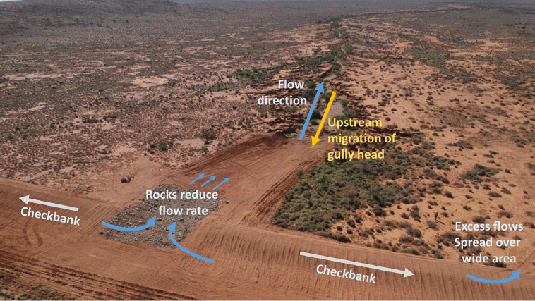
During 2021, Boolcoomatta recorded 205 mm of rainfall, with 95 mm over 2 days in November, plus an additional 28.3 mm at the beginning of February 2022. This resulted in notable upstream migration of gully heads (10–15 m) at Site 1. At the end of February 2022, after both rainfall events, checkbanks (raised soil mounds placed across the drainage line) were constructed at the head of the gully at Site 1, with the aim of channelling water through rocks to reduce flow rates (Fig. 3).
UAV data collection and processing
SfM-based DSMs were generated from visible-colour imagery collected using a DJI Phantom 4 Pro (Table 1). This UAV was equipped with a 20 MP, 1 inch CMOS sensor, with a 24 mm focal length (35 mm equivalent), the off-the-shelf specification for this UAV. All imaging runs were conducted using forward and side image overlaps of 85%, with the camera gimbal angle set to nadir (directly downwards). The DJI Ground Station Pro iPad app was used for the configuration of parameters and the automatic conduct of a typical ‘lawnmower’ survey pattern (Fig. 4a). The flight speed was determined automatically by the software to achieve the specified forward overlap of 85%. Imagery was collected at 35, 70 and 110 m above ground level, resulting in SfM-based DSMs with GSDs (ground sampling distances) of approximately 2, 4 and 6 cm. All SfM-based DSMs were processed in Agisoft Metashape Professional software (ver. 1.8.5, https://www.agisoft.com).
| Method | Complexity | Equipment used | Approximate cost of equipment | |
|---|---|---|---|---|
| SfM | Low complexity and skill level required; Capable with small UAVs that can be operated with minimal training; fully automated surveys | DJI Phantom 4 Pro (Consumer-level UAV); Propeller Aeropoints | A$10 000–A$15 000 (RTK UAV or non-RTK UAV + Aeropoints) | |
| LiDAR | Specialised skills required for data collection and processing; larger UAVs require additional certifications | DJI Matrice M600 Pro (Professional-level/specialty UAV); GeoSLAM Zeb Horizon multiple-return LiDAR; Propeller Aeropoints | ~A$60 000–A$90 000 (LiDAR, UAV and required equipment) |
Flight paths used for (a) visible colour and (b) LiDAR UAV surveys (Site 1, for example). Nine evenly positioned active ground control points were used for all surveys. The location of the ground control point acting as the base station (green) was placed on a fixed mark that acted as a reference datum used between imaging occasions. The mask (image subset area) used for data analysis can also be seen. A similar mask and ground control-point arrangement was used at Site 2.
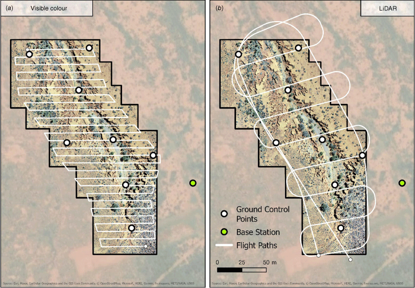
LiDAR data were captured using the GeoSLAM Zeb Horizon multiple-return LiDAR, mounted to a DJI Matrice 600 Pro (Table 1). Flight paths were specified as described in the instrument’s best-practices guide for data capture (Fig. 4b). All LiDAR surveys were conducted at 40 m above ground level with a flight speed of 4 m/s, resulting in LiDAR-based DSMs with GSDs of approximately 3 cm. Data from the Zeb Horizon was processed from a proprietary format into the open LAZ format. CloudCompare (ver. 2.12.0, 2022) was used for georeferencing and Agisoft Metashape Professional (ver. 1.8.5) was used for DSM generation.
Datasets from both methods were maintained as DSMs (land-surface and above-ground features, e.g. vegetation) and not converted to digital elevation models (ground-surface only) due to the high proportion of bare ground at the study site and the uncertainty associated with estimating the ground surface beneath vegetation.
Data were collected on the following three occasions: March 2021, May 2021 and March 2022. Both LiDAR-point clouds and visible-colour imagery (for SfM) were collected on the first occasion, whereas only visible-colour imagery was collected for the two successive occasions (Table 2). LiDAR data were collected at Site 1 and Site 2.
| Imaging occasion | SfM | LiDAR | |||
|---|---|---|---|---|---|
| Ground sampling distance (GSD) (cm) | |||||
| 2 | 4 | 6 | 3 | ||
| March 2021 | ⦁ | ⦁⦁ (+ Site 2) | |||
| May 2021 | ⦁⦁ | ⦁⦁ | ⦁⦁ | ||
| March 2022 | ⦁ | ||||
The number of datasets collected at each ground sampling distance (GSD) is indicated by black dots.
All datasets were masked (subset) to the same extent before analysis (Fig. 4). The masks were created to contain the erosion feature at each site, exclude inaccuracies at dataset edges and provide a consistent analysis area to compare datasets.
Ground control
Propeller Aeropoints were used as ground control to provide a consistent reference system to precisely geo-register (spatially align) each dataset. Propeller Aeropoints are solar powered active ground control points that use a post-process kinematic technique to obtain precise coordinates via a subscription-based corrections network transmitted over the mobile phone network (Propeller 2023).
To ensure that datasets captured on each occasion (Table 2) could be precisely co-registered, eight Propeller Aeropoints were distributed evenly across the imaging area prior to each flight, alongside additional highly reflective passive ground control points for LiDAR data collection (Fig. 4). The eight Aeropoints were placed 10–15 m inside the imaging area to ensure that each point was imaged approximately the same number of times (visible-colour imagery) and had similar LiDAR point density to maximise detectability and minimise co-registration errors. The Aeropoints were distributed evenly across the elevation profile to ensure that precise coordinates were obtained at multiple elevations. Because of the remoteness of the study location, the imaging sites fall outside of Propeller’s corrections network. As a result, an additional ninth Aeropoint was used as a base station for the eight main Aeropoints (Fig. 4) and was positioned at precisely the same location for each data-collection date. This base station was therefore processed with the same coordinates across imaging dates, providing highly accurate positioning relative to this point.
Analytical approaches
We conducted several analyses to address our aims. The analyses for ‘method precision’ were fundamental for addressing ‘method comparison’, ‘SfM resolution comparison’ and ‘change detection’, and are therefore also relevant in these sections.
The assessment of method precision is achieved by differencing DSMs from consecutive days, on the basis of the assumption that the ground surface remains unchanged over such a short period. No rain was recorded during any of the three imaging occasions. The term ‘precision’ is used as analyses concern the similarity of measurements from one day to the next, rather than a comparison to a ‘true’ elevation value (accuracy). Therefore, precision may also be interpreted as the uncertainty of elevation values (i.e. variation in measurements from one day to the next, with no change in ground surface).
SfM consistency was assessed separately for each of the three GSDs by using data collected on 5 and 6 May 2021. LiDAR consistency was assessed separately at Site 1 and Site 2, using data collected on the 16 and 17 March 2021 for Site 1, and on 16 and 18 March 2021 for Site 2. Precision was assessed using density plots, mean absolute difference (mean of elevation differences without regard to their sign, Eqn 1), bias (mean of elevation differences with regard to their sign; Eqn 2) and root mean squared error (RMSE, Eqn 3), where Z denotes an array of elevation values from all pixels in the study areas. Density plots were produced using the R package ggridges (Wilke 2022), where methods for plotting the density of difference values were derived from the base-R stats package (R Core Team 2022).
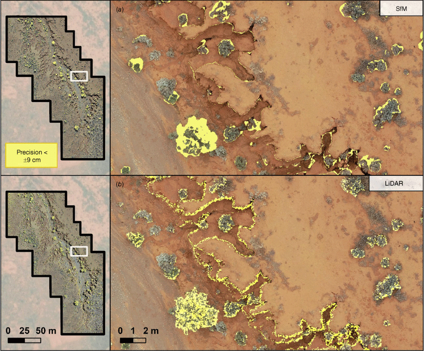
To understand the spatial distribution of errors across the study site, we conducted a threshold classification of LiDAR and SfM difference rasters to highlight areas where dataset precision is poor. We set the difference threshold on the basis of typical precisions achieved in comparable studies. As a result, a threshold of ±9 cm is used, as reported by Gillan et al. (2016). While Gillan et al. (2016) does not look specifically at gully erosion, and uses 12 cm GSD datasets, other studies with similarity to our research did not present precision values suitable for use as a threshold.
On the basis of results of this threshold classification, we produced density plots and calculated mean absolute error, bias and RMSE values separately for samples of three manually digitised surface types (vegetation, gully edges, and unvegetated surfaces). The number of polygons digitised per class ranged from 69 for unvegetated surfaces, to 126 for vegetation. The number of pixels that were sampled from within these polygons were equalised so that all classes had the same number of pixels as the smallest class (gully edges). This number of pixels varied depending on dataset GSD from ~70 000 (2 cm) to 7000 (6 cm). Metrics calculated at unvegetated surfaces were taken to be our final values of precision, because this surface type serves as the most similar comparison to other research, where RTK GNSS checkpoints at invariant features are used for precision assessment.
Elevation profiles were compared among the days described above as an additional method for assessing method precision. Profiles were calculated at two 20 m transects at Site 1.
Methods were compared by the comparison of density plots, precision metrics and elevation profiles between methods, as described above.
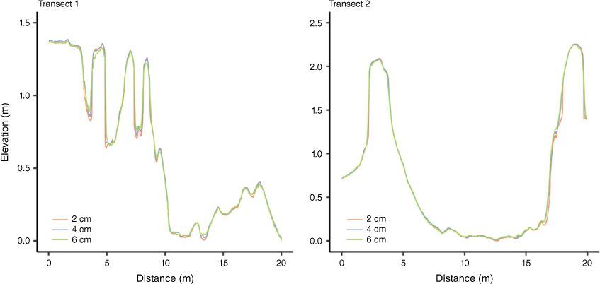
SfM-derived DSMs with 2, 4 and 6 cm GSDs were compared on the basis of the precision metrics, and by elevation profile comparison, as described above. Elevation profiles for all three GSDs were generated from DSMs collected on 5 May 2021.
Change in the erosion features at Site 1 over a 1 year period were assessed using SfM-based DSMs, because LiDAR data were collected only on the first imaging occasion (Table 2). We differenced SfM-derived DSMs with 2 cm GSDs between March 2021 and March 2022. Visual interpretation of the difference raster allowed an assessment of where and how much erosion has occurred. Volumetric loss of soil was also calculated for one area of notable erosion, and two additional 20 m transects (covering areas of most significant erosion) were used to assess change over the 1 year study period.
Results
Method precision
Across the entirety of Site 1, both LiDAR- and SfM-based datasets showed consistent mean absolute differences and RMSE values were high compared to site 2 (Table 3, Fig. 5). LiDAR precisions were also assessed at Site 2, where the RMSE and mean absolute difference was considerably lower (Table 3, Fig. 5).
| Method | GSD/site | Bias (cm) | Mean absolute difference (cm) | RMSE (cm) | |
|---|---|---|---|---|---|
| SfM | 2 cm | 3.20 | 3.68 | 18.2 | |
| 4 cm | 3.38 | 4.47 | 19.8 | ||
| 6 cm | 3.86 | 4.86` | 18.2 | ||
| LiDAR | Site 1 | −2.81 | 4.85 | 14.3 | |
| Site 2 | −0.147 | 2.35 | 5.27 |
For SfM-derived models, comparisons are made using three different GSDs. For LiDAR-derived models, comparisons are made using data from Site 1 and Site 2.
Density plots of elevation value differences between consecutive days for LiDAR- and SfM-derived elevation models. Data are grouped by GSD for SfM data, and by site for LiDAR data. Displayed values are limited to a density 0.5% of the maximum for each group. Quantile lines represent the 5th percentile, median and 95th percentile.
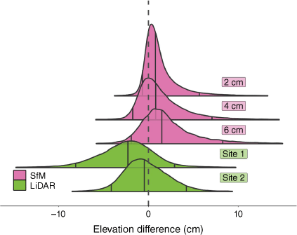
Fig. 6 shows areas where consecutive DSMs differ by more than 9 cm, indicating that areas of poor precision are concentrated at and around the edges of vegetation and along steep gully edges for both LiDAR and SfM methods.
Consistency of SfM- (a) and LiDAR-derived (b) DSMs between consecutive dates. Yellow areas indicate where DSMs differ by more than 9 cm.
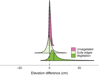
To further assess the sources of error within the elevation models, we separated difference values into three classes, using the 2 cm SfM dataset as an example. As is evident in Fig. 6, shrubs and gully edges are the greatest sources of variation in elevation values between days, whereas unvegetated surfaces exhibit a far smaller range of difference values (Fig. 7).
Density plots of elevation differences between consecutive days for SfM-derived elevation models with 2 cm GSD. Values are grouped by ground-surface classes for comparison. Displayed values are limited to a density 0.5% of the maximum for each group. Quantile lines represent the 5th percentile, median and 95th percentile.
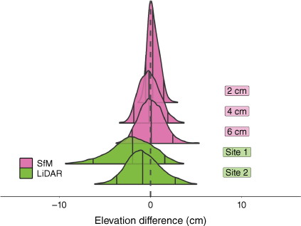
Therefore, assessing consistency values at unvegetated surfaces will provide an indication of method precision that is comparable to that in studies using RTK GNSS checkpoints of invariant features for precision assessment. When considering unvegetated surfaces only, elevation values between dates differ significantly less for both SfM and LiDAR, across all resolutions and sites (Table 4, Fig. 8), when compared to metrics taken across the whole site (Table 3, Fig. 5).
| Method | GSD/Site | Bias (cm) | Mean absolute difference (cm) | RMSE (cm) | |
|---|---|---|---|---|---|
| SfM | 2 cm | 0.34 | 0.54 | 0.72 | |
| 4 cm | −0.09 | 0.94 | 1.17 | ||
| 6 cm | 0.12 | 2.10 | 1.39 | ||
| LiDAR | Site 1 | −2.07 | 2.51 | 3.15 | |
| Site 2 | −0.75 | 1.68 | 2.08 |
For SfM-derived models, comparisons are made using three different GSDs. For LiDAR-derived models, comparisons are made using data from Site 1 and Site 2.
Density plots of the differences in elevation values between consecutive days for LiDAR- and SfM-derived elevation models at unvegetated surfaces only. Data are grouped by GSD for SfM data, and by site for LiDAR data. Displayed values are limited to a density 0.5% of the maximum for each group. Quantile lines represent the 5th percentile, median and 95th percentile.
While elevation profiles show some differences between consecutive dates for both methods, overall the consistency of elevation values at both transects remained high (Fig. 9).
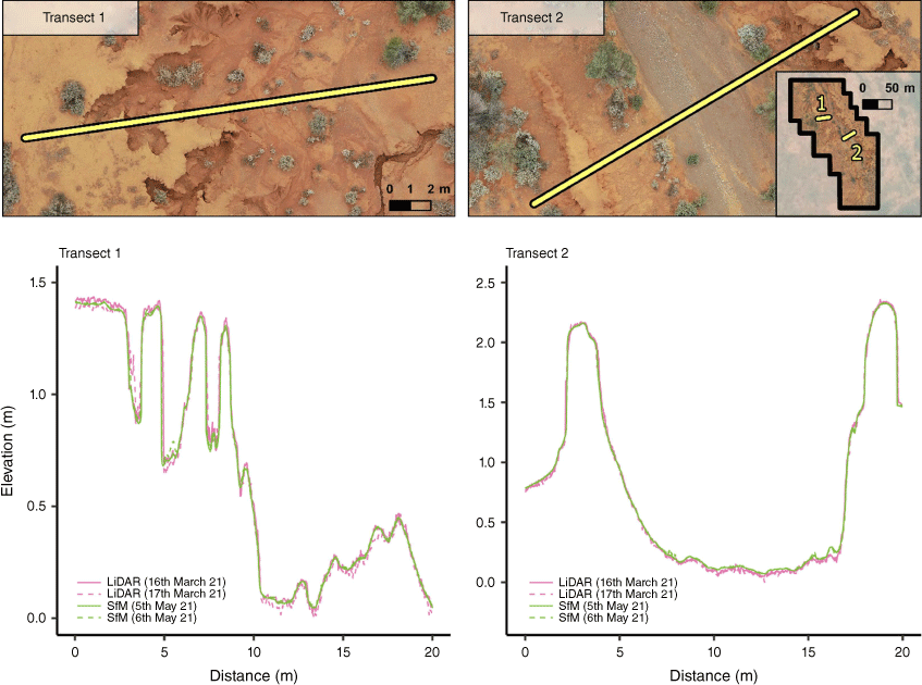
Method comparison
LiDAR and SfM datasets exhibited similar values for the calculated precision metrics, with RMSE values for SfM datasets being slightly lower than those of LiDAR (Table 4). These similarities are also evident in the density plots of difference values (Fig. 8). LiDAR- and SfM-based elevation values are reasonably consistent along both elevation profiles, with LiDAR datasets varying slightly more than SfM datasets at Transect 1 (Fig. 9). Gully edges in both SfM and LiDAR profiles are extremely similar, with their positions along the transects being effectively indistinguishable in the majority of cases.
SfM resolution comparison
Although the small number of repeated measurements does not allow for an analysis of statistical significance, RMSE values of SfM-based DSMs increase with an increasing GSD. Despite 2 cm datasets achieving the lowest RMSE values, RMSE values for 4 and 6 cm datasets remain very low. The similarity in elevation values among 2, 4 and 6 cm DSMs can also be seen in the density plots (Fig. 8) and in elevation profiles along Transects 1 and 2 (Fig. 10).
Change detection
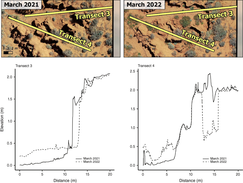
Fig. 11 shows areas of soil erosion and deposition across Site 1 between March 2021 and March 2022. The retreat of gully heads to the eastern side of the gully is evident in this map, providing an objective view for land managers of where the most significant erosion occurred after rainfall events in November 2021 and February 2022. Increased elevation values in the gully bottom directly beneath eroded edges owing to soil deposition are also evident (Fig. 11). The constructed checkbank (Fig. 3) is visible in this difference raster, as well as a large area of reduced elevation where gully edges were graded during checkbank construction. Volumetric erosion loss for the gully-edge area highlighted in Fig. 11 is 78.4 m3.
Gully erosion and deposition between March 2021 and March 2022, focussing on the area of most significant change. Change detection was conducted using 2 cm GSD DSMs. Transects 3 and 4 refer to the elevation profiles used to assess change in erosion. Note that extreme changes in elevation values at the southern end of the erosion gully are a result of the checkbank construction (see Fig. 3). Volumetric soil loss is calculated within the pink rectangle.
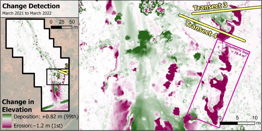
Comparing two elevation profiles at Transects 3 and 4 (Fig. 11), it is evident that the gully edge retreated by ~1.3 m in transect 3 (Fig. 12), whereas a 3 m section of earth was washed into the gully at Transect 4 (Fig. 12). The deposition of eroded soil can also be easily visualised, with ~20–30 cm of deposition in the low regions of both transects (Fig. 12).
Discussion
Method precision
Across the entirety of Site 1, both LiDAR- and SfM-based methods achieved RMSE values of ~14–20 cm (Table 3). Considering that previous research using DSM differencing for erosion mapping in similar environments reported precisions of ~8–9 cm (Martínez-Casasnovas et al. 2003; Gillan et al. 2016), the recorded values appear to be imprecise. However, it is clear that the presence of vegetation causes significant inaccuracies (Figs 6, 7), and that these inaccuracies contribute to high errors overall.
Therefore, to better understand the precision of these two methods, we focussed on invariant features (unvegetated surfaces), as in other studies using RTK GNSS checkpoints for accuracy assessment (Gillan et al. 2016; Koci et al. 2017; Anderson et al. 2023). When analyses are restricted to invariant features, RMSE values are far smaller across all methods, resolutions and sites (Table 4, Fig. 8) (0.72–3.15 cm). These values are considerably more precise than in other similar studies where RTK GNSS checkpoints were used (20–90 cm in Koci et al. (2017); 50 cm in Anderson et al. (2023); 9 cm in Gillan et al. (2016)). This may be a result of several factors. Dataset GSDs (6 cm at most) were smaller than those of Anderson et al. (2023)(12.6 cm), vegetation cover was significantly lower than the canopy-covered study location of Koci et al. (2017), and image overlaps for SfM-based DSM production were significantly higher than those used by Gillan et al. (2016) (60/30%, compared with 85/85%).
LiDAR achieved relatively high precisions at Site 2 compared to site 1, even when vegetation was included in the analysis (Table 3). When only flat areas were analysed, precision metrics became comparable to the values at Site 1 (Table 4). This suggests that the reason for the higher precisions for LiDAR at Site 2 (Table 3) was a result of differences in vegetation. This is consistent with the vegetation at Site 2 being generally shorter than that at Site 1, leading to smaller errors.
Method comparison
From the perspective of an operational monitoring program, the next question is whether LiDAR provides benefits for erosion monitoring that outweigh the additional cost and complexity over SfM-based methods that are achievable using off the shelf UAV+ sensor systems. LiDAR- and SfM-based DSMs exhibited similar precision metrics, with both methods achieving precisions significantly greater than in comparable research (Gillan et al. 2016; Koci et al. 2017; Anderson et al. 2023). RMSE values (Table 4) and density plots (Fig. 8) suggest that SfM-derived datasets were capable of achieving slightly higher precisions than were LiDAR-based datasets. The similarity between LiDAR and SfM is also clear when comparing elevation profiles between methods (Fig. 9).
Whereas both LiDAR- and SfM-derived DSMs have been shown to be precise, we are unable to conclude which dataset is most likely to represent the absolute true elevation. However, it is precision from one date to the next that is of the greatest importance in erosion monitoring. Also, regardless of which dataset may be presenting values closer to the absolute truth, any additional accuracy that may be achieved by a LiDAR-based approach must be weighed up against the practical and monetary benefits and limitations of each method. For widespread monitoring of erosion in isolated regions, it is likely that data collection will be undertaken by land managers who are not necessarily experienced in UAV-based data collection. Therefore, the greater expertise required to conduct LiDAR surveys should be noted. In favour of the use of LiDAR, a LiDAR point cloud takes less storage space than the equivalent visible-colour imagery (for an SfM approach), and requires less processing over large areas. However, the visible-colour imagery collected in the SfM workflow provides an additional dataset that can be used for monitoring a variety of additional ecological indicators (e.g. Retallack et al. (2023)). This means that despite increased data volume and processing requirements, an SfM-based approach to erosion monitoring may provide land managers with a better value proposition when put in the context of their overall monitoring needs. Despite this, it must be emphasised that the high precisions achievable in SfM-derived DSMs, as shown in this paper, are limited to a specific use case where vegetation cover is low, and the area of interest is not covered by canopy. Although a large proportion of the world’s rangelands is characterised by these landscapes, in regions with greater presence of tall vegetation, or where the overall vegetation cover is high, LiDAR is likely to serve as a far more precise approach. This can be seen in the results of Koci et al. (2017), where SfM-based DSMs with GSDs similar to those used in this study produced RMSE values of 0.23 m and greater in a highly vegetated study site.
SfM resolution comparison
Considering the use of an SfM-based approach for erosion monitoring, it is important to assess what GSD is necessary to capture erosion and achieve acceptable DSM precisions. Ideally, the lowest GSD able to answer the management question of interest would be the most favourable, because of reduced data size and processing time, as well as enabling shorter flight times or greater survey areas. This will differ depending on the size of the erosion feature being measured, and the rate at which change occurs. Changes in land surface after larger erosion events, such as those that occurred after significant rainfall at this study location, may be measurable with GSDs greater than 10 cm; however, more gradual erosion in between these main events would require finer resolutions. Therefore, if outright precision is required, then SfM-based DSMs with low GSDs may be favourable; otherwise, coarser resolutions remain capable of precisions greater than reported in comparable studies and greater than our equivalent LiDAR-based datasets.
Relevance of findings for management
The remote-sensing methods described in this paper provide a precise, spatially explicit and quantitative record of erosion severity and the volumetric soil loss from successive erosion events (Fig. 11), metrics that would otherwise be left to estimation by land managers. They also provide a tool for broader assessment across areas that are typically challenging to access. Continued monitoring with these methods will enable the detection and management of any further erosion and provide critical feedback on the effectiveness of remediation actions, such as checkbank construction or revegetation.
Conclusions
The recent rapid development of remote-sensing platform and sensor technologies, including UAVs and LiDAR, has increased their potential to be used for ecological monitoring and management. Specifically, these developments have greatly increased accessibility of three-dimensional data. In rangeland environments, the mapping of erosion gullies at fine spatial scales serves as an ideal candidate for the use of such data, with LiDAR and SfM representing two available methods. Our study demonstrated the feasibility of both LiDAR- and SfM-based approaches to produce highly precise DSMs of gully erosion in low-slope arid regions typical of a large part the world’s rangelands.
Similarities in LiDAR- and SfM-derived datasets opens serious consideration for the cost versus benefit of the use of LiDAR over SfM. At current levels of technological development, the complexity of LiDAR data collection and processing is significantly greater than that of SfM. Further, although monetary costs are subject to rapid change, the current cost of LiDAR greatly exceeds that of SfM. Because funding for rangeland management groups is often limited, and land managers typically do not have extensive experience in remote-sensing data collection, SfM can be considered as an option, not a compromise, compared with LiDAR, provided that canopy cover is not high. Additionally, the visible-colour imagery collected as part of the SfM process provides a dataset that may be useful in measuring a number of additional environmental condition indicators (e.g. vegetation cover, plant species abundance, frequency, density, etc.). For an SfM-based approach, flight parameters may be tuned to optimise imaging area and flight times if these characteristics are valued above outright precision. Considering these points, either of the two methods will enable arid gully erosion monitoring, allowing effective conservation and restoration of natural rangeland ecosystems into the future.
Data availability
R code used in analysis and figure production is available at the following URL. The corresponding author will provide data on request. doi.org/10.25909/25241893.
Author contributions
A. R., D. C., G. F., R. R. S., B. O., M. H., S. R., M. L.: conceptualisation. A. R., D. C., G. F.: data curation. A. R., D. C.: formal analysis. A. R., D. C.: investigation. A. R., D. C., G. F., R. R. S., B. O., M. H., S. R., M. L.: methodology. R. R. S., M. H.: project administration. R. R. S., D. C.: resources. A. R., D. C.: software. G. F., R. R. S., B. O., M. H., S. R., M. L.: supervision. A. R., D. C.: validation. A. R.: visualisation. A. R., D. C.: writing – original draft. A. R., D. C., G. F., R. R. S., B. O., M. H., S. R., M. L.: writing – review and editing.
Acknowledgements
We acknowledge the Adnyamathanha and Wilyakali people, the Traditional Owners of the lands on which this work was conducted. We recognise and respect the enduring relationship Traditional Owners have with their lands and waters, and we pay our respects to Elders past and present. We acknowledge the support of Bush Heritage staff and supporters from Boolcoomatta during fieldwork. We thank Steven Andriolo (URAF, The University of Adelaide) for his help in maintaining and organising all equipment used for data collection, including UAVs, sensors and active ground control, enabling the collection of high-quality data. We acknowledge GeoSLAM and Propeller for their support of the use of their equipment for research and educational purposes. This research was supported by an Australian Government Research Training Program (RTP) Scholarship and the Thyne Reid Foundation. This paper forms part of the PhD thesis submitted by Angus Retallack to the University of Adelaide.
References
Alexiou S, Deligiannakis G, Pallikarakis A, Papanikolaou I, Psomiadis E, Reicherter K (2021) Comparing high accuracy t-LiDAR and UAV-SfM derived point clouds for geomorphological change detection. ISPRS International Journal of Geo-Information 10, 367.
| Crossref | Google Scholar |
Alfonso-Torreño A, Gómez-Gutiérrez Á, Schnabel S (2021) Dynamics of erosion and deposition in a partially restored valley-bottom gully. Land 10, 62.
| Crossref | Google Scholar |
Anderson RL, le Roux J, van der Waal B, Rowntree K, Hedding DW (2023) Assessing the short-term inter-annual growth of the largest documented gully network in South Africa using UAV and SfM methodology. Physical Geography 1-23.
| Crossref | Google Scholar |
Booth DT, Tueller PT (2003) Rangeland monitoring using remote sensing. Arid Land Research and Management 17, 455-467.
| Crossref | Google Scholar |
Breshears DD, Whicker JJ, Johansen MP, Pinder JE (2003) Wind and water erosion and transport in semi-arid shrubland, grassland and forest ecosystems: quantifying dominance of horizontal wind-driven transport. Earth Surface Processes and Landforms 28, 1189-1209.
| Crossref | Google Scholar |
Bureau of Meteorology (2010) Average annual, seasonal and monthly rainfall (Ed. Bureau of Meteorology). Available at http://www.bom.gov.au/jsp/ncc/climate_averages/rainfall/index.jsp
Bush Heritage Australia (2019) Boolcoomatta. Available at https://www.bushheritage.org.au/places-we-protect/south-australia/boolcoomatta
Chakrabortty R, Pal SC (2023) Systematic review on gully erosion measurement, modelling and management: mitigation alternatives and policy recommendations. Geological Journal 58, 3544-3576.
| Crossref | Google Scholar |
Desir G, Marín C (2007) Factors controlling the erosion rates in a semi-arid zone (Bardenas Reales, NE Spain). CATENA 71, 31-40.
| Crossref | Google Scholar |
D’Oleire-Oltmanns S, Marzolff I, Peter K, Ries J (2012) Unmanned aerial vehicle (UAV) for monitoring soil erosion in Morocco. Remote Sensing 4, 3390-3416.
| Crossref | Google Scholar |
Dwivedi RS, Sankar TR, Venkataratnam L, Karale RL, Gawande SP, Rao KVS, Senchaudhary S, Bhaumik KR, Mukharjee KK (1997) The inventory and monitoring of eroded lands using remote sensing data. International Journal of Remote Sensing 18, 107-119.
| Crossref | Google Scholar |
Elaloui A, Khalki EME, Namous M, Ziadi K, Eloudi H, Faouzi E, Bou-Imajjane L, Karroum M, Tramblay Y, Boudhar A, Chehbouni A (2023) Soil erosion under future climate change scenarios in a semi-arid region. Water 15, 146.
| Crossref | Google Scholar |
Fadul HM, Salih AA, Ali IA, Inanaga S (1999) Use of remote sensing to map gully erosion along the Atbara River, Sudan. International Journal of Applied Earth Observation and Geoinformation 1, 175-180.
| Crossref | Google Scholar |
Gillan JK, Karl JW, Barger NN, Elaksher A, Duniway MC (2016) Spatially explicit rangeland erosion monitoring using high-resolution digital aerial imagery. Rangeland Ecology & Management 69, 95-107.
| Crossref | Google Scholar |
Gómez Gutiérrez Á, Schnabel S, Lavado Contador F, De Sanjosé JJ, Atkinson ADJ, Pulido-Fernández M, Sánchez Fernández M (2018) Studying the influence of livestock pressure on gully erosion in rangelands of SW Spain by means of the UAV+ SfM workflow. Boletín de La Asociación de Geógrafos Españoles 2018, 66-88.
| Crossref | Google Scholar |
Guan Y, Yang S, Zhao C, Lou H, Chen K, Zhang C, Wu B (2021) Monitoring long-term gully erosion and topographic thresholds in the marginal zone of the Chinese Loess Plateau. Soil and Tillage Research 205, 104800.
| Crossref | Google Scholar |
Hout R, Maleval V, Mahe G, Rouvellac E, Crouzevialle R, Cerbelaud F (2020) UAV and LiDAR data in the service of bank gully erosion measurement in Rambla de Algeciras lakeshore. Water 12, 2748.
| Crossref | Google Scholar |
Jeanneau AC, Ostendorf B, Herrmann T (2019) Relative spatial differences in sediment transport in fire-affected agricultural landscapes: a field study. Aeolian Research 39, 13-22.
| Crossref | Google Scholar |
Johansen K, Taihei S, Tindall D, Phinn S (2012) Object-based monitoring of gully extent and volume in north Australia using LiDAR data. Proceedings of the 4th GEOBIA 25, 168-173.
| Google Scholar |
Jones A (2000) Effects of cattle grazing on North American arid ecosystems: a quantitative review. Western North American Naturalist 60, 155-164.
| Google Scholar |
Khalili Moghadam B, Jabarifar M, Bagheri M, Shahbazi E (2015) Effects of land use change on soil splash erosion in the semi-arid region of Iran. Geoderma 241–242, 210-220.
| Crossref | Google Scholar |
Koci J, Jarihani B, Leon JX, Sidle R, Wilkinson S, Bartley R (2017) Assessment of UAV and ground-based structure from motion with multi-view stereo photogrammetry in a gullied savanna catchment. ISPRS International Journal of Geo-Information 6, 328.
| Crossref | Google Scholar |
Martínez-Casasnovas JA, Antón‐Fernández C, Ramos MC (2003) Sediment production in large gullies of the Mediterranean area (NE Spain) from high-resolution digital elevation models and geographical information systems analysis. Earth Surface Processes and Landforms 28, 443-456.
| Crossref | Google Scholar |
Molnar P (2001) Climate change, flooding in arid environments, and erosion rates. Geology 29, 1071-1074.
| Crossref | Google Scholar |
Perroy RL, Bookhagen B, Asner GP, Chadwick OA (2010) Comparison of gully erosion estimates using airborne and ground-based LiDAR on Santa Cruz Island, California. Geomorphology 118, 288-300.
| Crossref | Google Scholar |
Propeller (2023) Propeller Aeropoints. Available at https://www.propelleraero.com/aeropoints/
R Core Team (2022) ‘R: a language and environment for statistical computing.’ (R Foundation for Statistical Computing: Vienna, Austria) Available at https://www.R-project.org/
Retallack A, Finlayson G, Ostendorf B, Clarke K, Lewis M (2023) Remote sensing for monitoring rangeland condition: current status and development of methods. Environmental and Sustainability Indicators 19, 100285.
| Crossref | Google Scholar |
Searle R (2021) ‘Australian Soil Classification Map. Version 1.0.0.’ (Terrestrial Ecosystem Research Network) 10.25901/edyr-wg85.
Soil Science Australia (2023) Calcarosols [CA]. The Australian Soil Classification. Available at https://www.soilscienceaustralia.org.au/asc/ca/calcsols.htm
UN EMG (2011) Global drylands: a UN system-wide response. Available at https://www.unep-wcmc.org/resources-and-data/global-drylands--a-un-system-wide-response
Vrieling A (2006) Satellite remote sensing for water erosion assessment: a review. CATENA 65, 2-18.
| Crossref | Google Scholar |
Vrieling A, Rodrigues SC, Bartholomeus H, Sterk G (2007) Automatic identification of erosion gullies with ASTER imagery in the Brazilian Cerrados. International Journal of Remote Sensing 28, 2723-2738.
| Crossref | Google Scholar |
Wilke C (2022) ggridges: ridgeline plots in ‘ggplot2’. Ver. 0.5.4. Available at https://CRAN.R-project.org/package=ggridges
Yang S, Guan Y, Zhao C, Zhang C, Bai J, Chen K (2019) Determining the influence of catchment area on intensity of gully erosion using high-resolution aerial imagery: a 40-year case study from the Loess Plateau, northern China. Geoderma 347, 90-102.
| Crossref | Google Scholar |