

The Mark II Bromilow Kinnear humane soft trap: a major upgrade
J. E. Kinnear A , R. N. Bromilow B D and N. Moore CA 9 Valley Road, Wembley Downs, WA 6019, Australia.
B PO Box 159, Kellerberrin, WA 6410, Australia.
C Department of Parks and Wildlife, PO Box 332, Merredin, WA 6415, Australia.
D Corresponding author. Email: bob.bromilow@bigpond.com
Australian Mammalogy 36(1) 121-127 https://doi.org/10.1071/AM13023
Submitted: 5 July 2013 Accepted: 21 January 2014 Published: 12 March 2014
Abstract
The Bromilow soft trap was originally created to counter the propensity of black-flanked rock-wallabies (Petrogale lateralis lateralis, hence black-flanked) to harm themselves in wire traps. It achieved that goal commendably and has proven to be durable and versatile as it is also suitable for trapping other medium-sized mammals. Major improvements have been incorporated without altering the basic design thus enabling existing traps to be readily upgraded.
The traps are now 15% lighter, and easier to set with a new more reliable trigger. The shroud has been discarded, and it now folds more compactly for transport and storage. The capture chamber is constructed of new materials designed to enable an animal to be extracted more readily.
These modifications are described in detail along with illustrations. For anyone intending on building a new trap, free professional-grade architectural drawings of the framework and components are available via the web (see text).
Additional keywords: improved humane live trap, medium-sized mammals.
Introduction
The primary rule in trapping wildlife should be an ethical one as exemplified by quoting a precept – Primum non-nocere – ‘First, do no harm’. Apart from achieving this goal, other benefits accrue from a modelling aspect; the fewer traumas associated with capturing an animal, the greater the probability of generating a more useful capture history and more reliable statistics. Live trapping, whereupon an individual is marked, released and recaptured (preferably repeatedly), can be a productive method because, apart from providing population estimates, it can also provide other vital statistics of interest (Kinnear et al. 1988, 2002, 2010; Krebs 1999).
Historical background
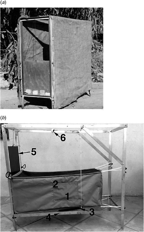
During the initial stages of the Wheatbelt rock-wallaby project, our first effort to capture black-flanked rock-wallabies (Petrogale lateralis lateralis) using wire-cage traps resulted in non-fatal self-inflicted injuries. Only two individuals were caught, but this experience led us to suspend our trapping endeavours pending the subsequent development of the original Mark 1 Bromilow soft trap (Kinnear et al. 1988) (Fig. 1a).
|
The Mark 1 Bromilow model has served us well; during the course of the first phase of the rock-wallaby project (1978–98), more than 1700 rock-wallabies were caught without a fatality nor were there injuries apart from an occasional abrasion. It has proven to be a versatile design as it has been used to capture tammar wallabies (Macropus eugenii), woylies (Bettongia penicillata), and common brush-tail possums (Trichosurus vulpecula). Furthermore, it has been widely copied, and it has stimulated others to build and use other versions of humane soft traps (see Di Stefano et al. 2005).
As time passed, however, it became clear that there was scope for changes and improvements and these have been addressed without major changes to the basic design; any Mark I can incorporate the changes using the existing framework.
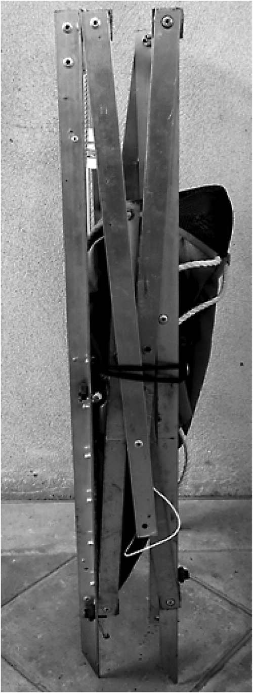
The redesigned Mark 2 incorporates several changes and new features (Fig. 1b). Some examples are: the wrap-around shroud has been discarded; it weighs less (820 g), the trigger is much more convenient to set and is more reliable, and its sensitivity can be adjusted. When folded, there is provision to neatly secure it in a more compact configuration (Fig. 2).
|
The most significant improvements, however, are a new trigger and a design change that enables one to extricate an animal with relative ease and, therefore, with less stress on all concerned. This feature required the capture chamber to be modified extensively and will be described in detail separately.
The original basic design
The basic features of the original Mark I (Fig. 1a) (Kinnear et al. 1988) consisted of an aluminum framework fixed to an aluminum doorframe, with a capture chamber consisting of small-meshed fish-netting shaped like a slightly tapered blind windsock. The netting was attached to the entrance doorframe and suspended by ropes to the rear of the frame. When a trap was set, the open entrance consisted of an elevated aluminum ‘drop-door’ (padded at the bottom edge) aligned within slotted guides along the sides of the doorframe; it was suspended by a cord linked to a magnet that gripped a matching piece of metal affixed to a wooden ‘trip-plate’.
Setting a trap consisted of connecting the magnet to the hinged trip-plate so that the ‘cocked’ plate made contact with the bottom of the meshed chamber. On entering the chamber seeking a lure, an animal would step on the trip-plate, breaking the magnetic contact and so allowing the door to drop, blocking the entrance.
The humane benefits of this design stemmed from the pliant nature of the suspended soft netting. Any agitated animals lunging in an effort to escape were thus cushioned from injury. It was rare for an animal to make contact with the aluminum door especially if care was taken to approach the trap from the entrance. New features have reduced the risk of injury even further.
In the following, we list the new components (Tables 1, 2) with relevant details and provide photographs to illustrate the new features. A detailed architectural drawing of the frame is available by requesting a copy via email to the following address: library@dpaw.wa.gov.au. There are no fees or restrictions.

|

|
Methods and materials
Modifications and changes
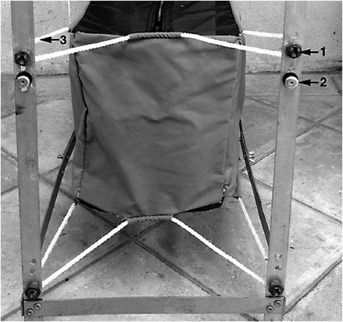
The two upper framework bars have been slightly modified on each side by eliminating one of the fasteners (6 × 18-mm gutter bolts with wing nuts; finger tight) (Fig. 3) that were formerly used to to secure Mark 1 traps in a working configuration. We recommend this design change for both the Mark I and newly constructed traps as it simplifies and facilitates the erection of traps. One less task is always welcomed by anyone who has to set out 30–40 traps.
|
Comments
The adoption of a polyethylene sliding drop-door and trip-plate represents a weight-saving, and a significant cost-saving, benefit (Fig. 4). Aluminium and wooden marine ply remains an option that works equally well, but adds expense and weight. We elected nevertheless, to use aluminium as a material for the trip-plate hinge as opposed to mild steel for durability and ease of attachment to the trip-plate, the former being important if the traps are used in a marine island environment.
|
Magnets
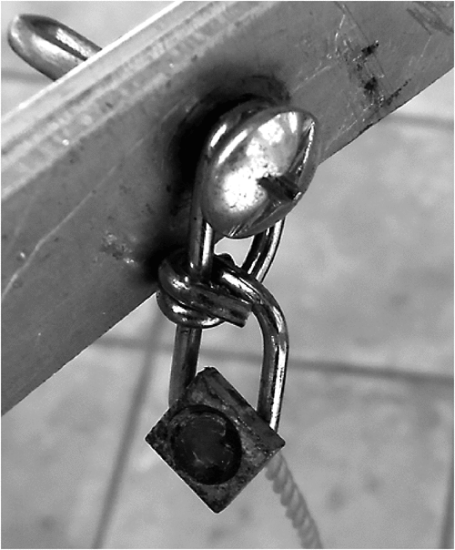
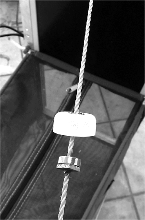
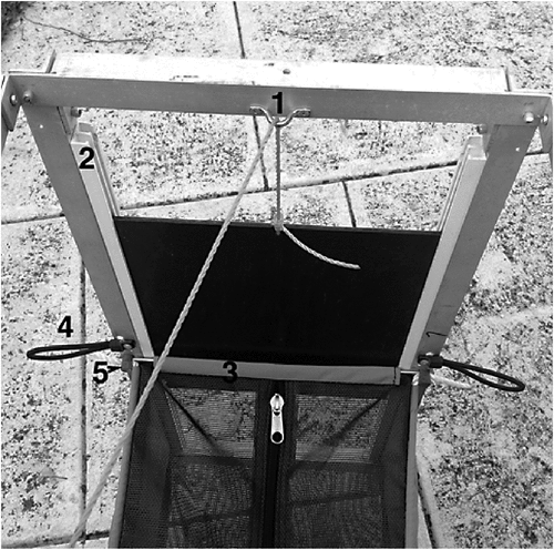
Neodymium magnets are the strongest permanent magnets made and thus can be of compact size. It is necessary to use a countersunk torus-type shaped in order to attach it to the suspension cord component of the trigger system supporting the door (see parts list, Table 2; Fig. 5). The trigger sensitivity can be adjusted by inserting non-magnetic spacers between the magnet and its contact. To increase the triggering threshold one can use a larger magnet or attach a magnet to the trip-plate cord instead of magnetically receptive metal. We have set our trap to trigger 700–800 g. The minimum magnetic strength is governed by the weight of the drop-door, which can be made lighter by using thinner material should a trap be used on smaller species.
|
Protecting the magnet
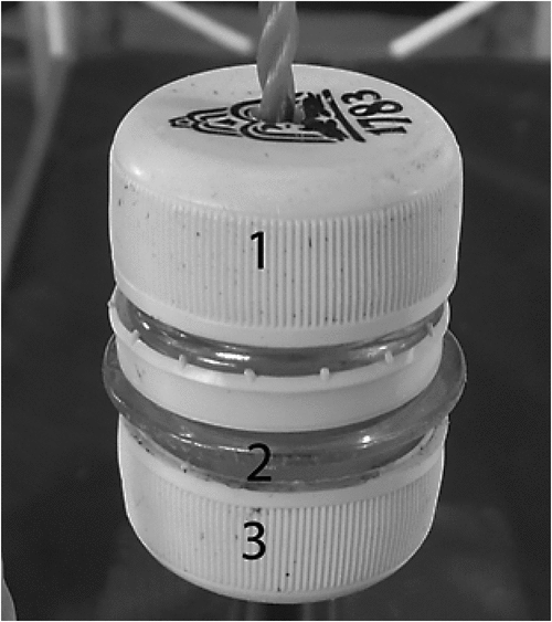
Neodymium magnets are a composite containing sintered NdFe14B, and are noted for their coercivity (i.e. resistance to demagnetism, which makes them extremely durable). Since these materials are prone to oxidation they require a protective coating (typically nickel/copper-nickel). Notwithstanding their robustness, they can, however, be damaged by forceful contact such as, when on triggering, the magnet (being attached to the drop-door) flies forward, potentially making contact with the aluminium frame. To protect the working magnet, we have enclosed it within a plastic bottle cap (a 1.25-L fruit juice bottle cap works well: Fig. 5). During storage, we have taken further steps to protect it by fully enclosing it using the same recycled materials and storing it in the side pocket (see Figs 1b, 6).
|
Connecting the trigger system
The fully set trap suspending the door is illustrated in Fig. 5 by mating the magnet with a metal nut. The nut and cord (Fig. 3) are threaded through a chain link guide held in place by the fastener used when erecting a trap (Table 2). When triggered, the nut is restrained to facilitate resetting (as illustrated).
The Mark I capture chamber
The original Mark I chamber consisted of netting that visually exposed the lure (apple) to interested rock-wallabies (Kinnear et al. 1988). The rock-wallabies soon learned to attack the lure from the outside and, in doing so, they frequently triggered the trap. It was not unusual to find an empty trap with the door closed and the lure reduced to a damp spot.
The remedy that countered this behaviour was to wrap a shroud around the three sides – initially hessian (Fig. 1a); later, dense shade cloth for durability – but this added weight, and often made the trigger unreliable due to the shade cloth shroud flapping against the trigger cord and triggering the trap in strong windy conditions. Moreover, under certain circumstances, traps could be blown over by strong gusty winds buffeting the shroud’s large surface area.
The new capture chamber
The new capture chamber is essentially a bag with the sides and the rear panels made of opaque canvas or polyester material (Figs 1b, 7, 8). We prefer the latter as it is lighter and not prone to shrinkage. It is made UV resistant as it is commonly used as a cover material to protect stored caravans, cars, boats, etc., exposed to the elements (Table 2).
|
|
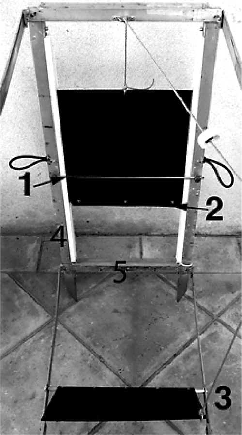
The top and bottom panels consist of dense mesh (‘Breezeway’) for ventilation and drainage. The top mesh panel incorporates a heavy-duty zipper doubly stitched centrally along the full length of the mesh, which, when appropriately unzipped, greatly facilitates the extrication of an animal (Figs 8, 9; Table 2).
|
Dimensions of bag
The dimensions (in millimetres) of the slightly tapered bag are: length 755; width 320 (front), 280 (rear); depth 310 (which conform to the doorframe dimensions). Along the entire edges of the bag, top and bottom, a loop must be built in to accommodate the suspension ropes (6 mm diameter) that are threaded through to suspend the bag to the frame at both ends. A short retaining loop is also required at the top and bottom of the rear panel (Figs 7–9).
Attaching the bag to the door frame
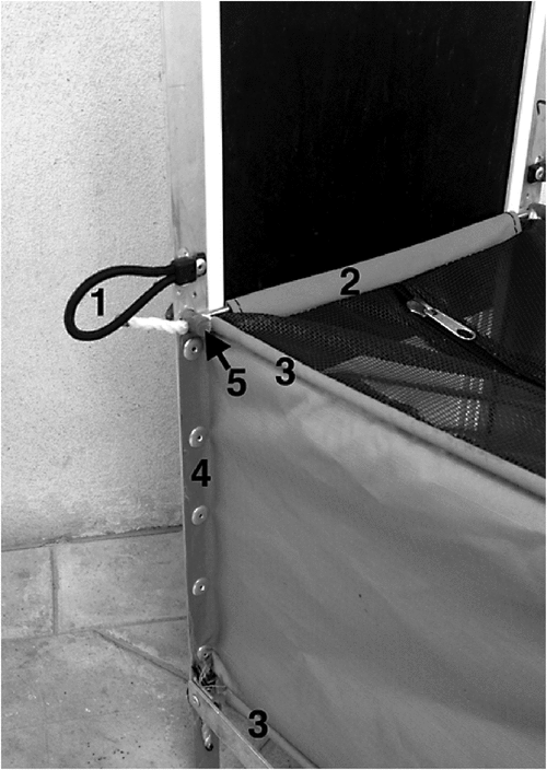
This step is critical: we have provided photographs (Figs 8, 9) to complement the following description. The top mesh is curled over and so stitched to form a loop that is padded with the fabric used for the sides. The loop accommodates a 5-mm diameter × 365-mm length stainless steel rod (Fig. 4) that is inserted and secured to the doorframe by split-bolt fasteners (Fig. 8; Table 2), which are also used to clamp the rope on each side. Stainless steel is used to provide the necessary rigidity, given the small diameter of the rod.
The bottom floor mesh is secured by aluminum pop-rivets to the bottom frame member, and the threaded suspension ropes are clamped by split bolts, as described above (Figs 8, 9). The zipper (No. 10, spiral) is centrally double-stitched along the entire length of the top mesh and should always open from front to back (Fig. 9).
The two side panels are so constructed that flaps can be deflected outward 90°, which are then secured to the doorframe by wide-flanged rivets (Fig. 8). All of these features should be built in during the fabrication of the bag with the suspension rope threaded in place ready for attachment.
Advice on the use of the trap
We typically set out traps that are ‘free-baited’ for three days with the door tied open. A small amount of ‘lead-up’ lure is placed in front of the entrance, and likewise midway in the chamber with most of the lure placed at the rear. Traps with a captured animal are approached from the front. The zipper is then partly opened and the animal manipulated so that can be grasped appropriately – typically, for larger macropods, at the base of the tail – whereupon it is then readily removed after the zipper is fully unzipped.
Before storage, the trap chamber, in particular, should always be washed, dried and stored in a dry environment.
Concluding remarks
The new Bromilow Kinnear trap remains a versatile humane trap with many new features and improvements that has made it more humane, reliable, and more convenient to use and store. It is scalable and readily customised for different species, e.g. triggering threshold. Adopters and users are encouraged to be innovative and to publish any improvements. Correspondence from interested parties would be welcomed.
Acknowledgements
We gratefully acknowledge the contributions made by the late Bob Pollard who constructed the bag and patiently endured requests for seemingly endless changes. We are indebted to Nathan Greenhill, Coordinator of Recreation and Landscape unit, for the professional architectural drawings that are available on request (see text). Craig Pentland kindly tested numerous versions in the field and provided helpful advice.
The trap was inspected by the Animal Ethics Committee and judged to have no animal welfare issues. The committee commended the authors for their endeavours to improve an existing humane trap.
References
Di Stefano, J., Moyle, R., and Coulson, R. (2005). A soft-walled double-layered trap for capture of swamp wallabies Wallabia bicolor. Australian Mammalogy 108, 235–238.Kinnear, J. E., Onus, M. L., and Bromilow, R. N. (1988). Fox control and rock-wallaby population dynamics. Australian Wildlife Research 15, 435–450.
| Fox control and rock-wallaby population dynamics.Crossref | GoogleScholarGoogle Scholar |
Kinnear, J. E., Sumner, N. R., and Onus, M. L. (2002). The red fox in Australia – an exotic predator turned biocontrol agent. Biological Conservation 108, 335–359.
| The red fox in Australia – an exotic predator turned biocontrol agent.Crossref | GoogleScholarGoogle Scholar |
Kinnear, J. E., Krebs, C. J., Pentland, C., Orell, P., Holme, C., and Karvinen, R. (2010). Predator-baiting experiments for the conservation of rock-wallabies in Western Australia: a 25-year review with recent advances. Wildlife Research 37, 57–67.
| Predator-baiting experiments for the conservation of rock-wallabies in Western Australia: a 25-year review with recent advances.Crossref | GoogleScholarGoogle Scholar |
Krebs, C. J. (1999). ‘Ecological Methodology’ 2nd edn. (Addison-Wesley Longman: California, USA.)