

Electrochemical Reduction of 2,4-Dinitrotoluene in Room Temperature Ionic Liquids: A Mechanistic Investigation*
Junqiao Lee A , Catherine E. Hay A and Debbie S. Silvester A BA Curtin Institute for Functional Molecules and Interfaces, and School of Molecular and Life Sciences, Curtin University, GPO Box U1987, Perth, WA 6845, Australia.
B Corresponding author. Email: d.silvester-dean@curtin.edu.au
Australian Journal of Chemistry 71(10) 818-825 https://doi.org/10.1071/CH18315
Submitted: 3 July 2018 Accepted: 9 August 2018 Published: 12 September 2018
Abstract
The reduction mechanism of 2,4-dinitrotoluene (DNT) has been studied in eight room temperature ionic liquids (RTILs) using cyclic voltammetry (CV), square wave voltammetry (SWV), chronoamperometry, and digital simulation. Two distinctive peaks are observed in the voltammetry, corresponding to the stepwise reduction of the two nitro groups on the aromatic ring. Diffusion coefficients (D) and electron counts (n) were calculated from chronoamperometric transients, revealing an electron count of one in most RTILs, and a linear relationship between D and the inverse of viscosity. Focusing on the first reduction only, the peak appears to be chemically reversible at low concentrations. However, as the concentration increases, the current of the reverse peak diminishes, suggesting that one or more chemical steps occur after the electrochemical step. The results from digital simulation of the CVs in one of the RTILs reveal that the most likely mechanism involves a deprotonation of the methyl group of a parent DNT molecule by the electrogenerated radical anion and/or a dimerisation of two electrogenerated radical anions. Elucidation of the reduction mechanism of DNT (and other explosives) is vital if electrochemical techniques are to be employed to detect these types of compounds in the field.
Introduction
2,4-Dinitrotoluene (DNT) is a pale yellow solid, and is a well known precursor to the highly explosive 2,4,6-trinitrotoluene (TNT). It is often found as an impurity in TNT samples,[1] typically around 1 wt-% in a solid sample and up to 38 wt-% in a sublimed sample. The higher vapour pressure of DNT compared with TNT means that DNT is often used as a fingerprint to detect concealed TNT explosive samples.[1] DNT itself is highly toxic and is identified as hazardous by the environmental protection agency.[2] It is commonly found in groundwater, surface water, and soil at waste sites, e.g. near facilities that manufacture or process explosives, or those that contain buried ammunitions waste.[2] Due to its hazardous nature, the ability to identify and quantify DNT is of much importance from both a safety and an environmental remediation point of view.
Electrochemistry has been identified as a viable method for the onsite detection of explosives due to its low-cost, portability, high sensitivity and selectivity, durability, and low power requirements.[3–6] Nitroaromatic compounds are ideal candidates for electrochemical detection due to their easily reducible nitro groups that give rise to a distinct current response. When designing an electrochemical sensor, it is important to study the reaction mechanisms involved in the reduction processes, to understand their contribution to the observed current, and identify any electrogenerated products that may accumulate at the electrode surface, which in turn can affect the sensor response.
The electrochemical reduction of 2,4-DNT has previously been studied in both protic and aprotic solvents. In protic solvents, the generally accepted mechanism is the reduction of the nitro groups of DNT to hydroxylamine or amine groups, depending on the pH of the solution.[7–9] However, the mechanism is different in aprotic solvents (e.g. acetonitrile or DMF),[7,8,10] where DNT is reduced by one electron to the radical anion in the first step, and in the second step to the dianion. Follow-up chemical reactions are often observed for these highly basic species at more negative potentials.
Despite their wide use, conventional electrochemical solvents can suffer from issues such as high volatility, narrow electrochemical windows, and possible interactions with analyte species, and so alternative solvents are sought. Room temperature ionic liquids (RTILs) have been regarded by electrochemists as a replacement electrochemical solvent, and as a result, many electrochemical investigations have been carried out in RTILs over the last 15 years.[11–13] They possess general properties such as intrinsic conductivity, high thermal and chemical stability, low volatility, wide electrochemical windows, high polarity, and good solvation abilities, that make them promising solvents for the electrochemical detection of a wide range of analytes.[14–18] The electrochemical detection of DNT in RTILs (using cyclic and square-wave voltammetry) has previously been reported,[19,20] however the detailed reaction mechanism for DNT reduction in RTILs has not yet been studied. The aim of the current study is therefore to fill this knowledge gap and elucidate the electrochemical mechanisms occurring at the working electrode. To achieve this, several different RTILs are studied as solvents, and a range of electrochemical techniques are employed.
Experimental
Chemicals and Reagents
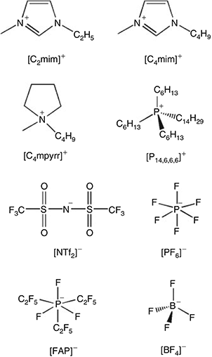
The RTILs 1-ethyl-3-methylimidazolium bis(trifluoromethylsulfonyl)imide ([C2mim][NTf2]), 1-butyl-3-methylimidazolium bis(trifluoromethylsulfonyl)imide ([C4mim][NTf2]), N-butyl-N-methylpyrrolidinium bis(tri-fluoromethylsulfonyl)imide ([C4mpyrr][NTf2]), and 1-butyl-3-methylimidazolium tetrafluoroborate ([C4mim][BF4]) were obtained from IoLiTec (Heilbronn, Germany) at the highest purity available (> 99.5 %). The RTILs 1-hexyl-3-methylimidazolium trifluorotris(pentafluoroethyl)phosphate ([C6mim][FAP]), 1-butyl-3-methylimidazolium hexafluorophosphate ([C4mim][PF6]), and trihexyltetradecylphosphonium pentafluoroethyltrifluorophosphate ([P14,6,6,6][FAP]) were purchased from Merck KGaA (Kilsyth, Victoria, Australia) at the highest purity available (<99 %), and the RTIL trihexyltetradecyl-phosphonium bis(trifluoromethylsulfonyl)imide ([P14,6,6,6][NTf2]) was kindly donated by Prof Chris Hardacre (now at the University of Manchester, UK) when he was located at Queens University Belfast, UK. The chemical structures of the cations and anions are given in Fig. 1. All RTILs were used as received. However, the blank voltammetry of all RTILs was tested to ensure that there were no obvious voltammetric features from impurities within the available potential window.
|
2,4-Dinitrotoulene (DNT) was purchased from Cerilliant Corporation (Round Rock, Texas, USA) as a solution of 1000 μg mL−1 in acetonitrile. Nitrogen gas (N2, >99.99 %, BOC gas, Welshpool, WA, Australia) was used for purging of the set-up. Ferrocene (Fc, Fe(C5H5)2, 98 % purity) and tetra-N-butylammonium perchlorate (TBAP, 98 % purity) were from Sigma–Aldrich. Acetonitrile (MeCN, Sigma–Aldrich, 99.8 %), methanol (Sigma–Aldrich, 99.9 %), acetone (Sigma–Aldrich, 99.9 %), and ultrapure water (resistance = 18.2 MΩ cm, prepared by an ultrapure laboratory water purification system from Millipore Pty Ltd, North Ryde, NSW, Australia) were used as rinsing solvents.
Sample Preparation
A suitable aliquot (~25 μL) of the stock DNT solution was precisely measured into a clean glass vial and the acetonitrile was allowed to evaporate overnight under vacuum. The RTIL was then added at an appropriate volume (measured accurately by weight) to make up the required concentrations. Ferrocene (Fc) was added at the end of the experiment to calibrate the reference potential. This was done by dropping a small amount of solid ferrocene into the nitroaromatic/RTIL solution already on the electrode, using an Eppendorf pipette tip. After the Fc was added, the RTIL was gently stirred with the pipette tip to aid dissolution. The analyte peak potentials were then shifted to ensure that the midpoint of ferrocene/ferrocenium was 0 V.
Instrumental
A PGSTAT101 Autolab potentiostat (Eco Chemie, Netherlands), interfaced to a PC with NOVA software, was employed to conduct electrochemical experiments, carried out inside a custom-made aluminium Faraday cage placed in a fume cupboard. The temperature of the laboratory was maintained at 294 ± 1 K. A scan rate of 100 mV s−1 was typically employed on the gold microelectrode, and 10 mV s−1 on the gold thin-film electrodes. Optimized square wave voltammetry (SWV) parameters were: amplitude of 20 mV and frequency of 50 Hz.
Microelectrode Experiments
The working electrode was a homemade gold microelectrode, made of a gold micrometer-sized wire encased and sealed within a glass body. A conventional two-electrode arrangement was employed, with a 0.5 mm diameter silver wire (Sigma–Aldrich) used as a combined counter electrode and (quasi-)reference electrode. The radius of the working electrode (13 μm) was calibrated electrochemically with a solution of 3 mM ferrocene in acetonitrile with 0.1 M TBAP as background electrolyte (diffusion coefficient 2.3 × 10⁻⁹ m2 s−1 at 298 K).[21] Microlitre quantities (~20 μL) of RTILs were contained within a reservoir at the tip of the electrode. The electrodes were setup inside a glass ‘T-cell’[22] in a controlled atmosphere under constant N2-gas flow (at 480 sccm). Before each experiment, the microelectrode was polished with alumina powder of decreasing size (3, 1, and 0.5 μm, Kemet, NSW, Australia) on soft lapping pads (Buehler, Lake Bluff, IL). The cell containing the RTIL/analyte sample was purged under high vacuum (Edwards high vacuum pump, Model ES 50) to remove oxygen and dissolved atmospheric moisture for > 1 h, before introducing the N2 gas.
Chronoamperometric transients were obtained on the microdisk electrode for a duration of 5 s with a sample time of 0.01 s. The potential was held for 30 s just before the onset of the peaks in the cyclic voltammetric scans, before stepping it to a potential after the reduction peak and holding for 5 s. Chronoamperometric transients were regression fitted with the Shoup and Szabo equation[23] using the software package Origin 6.0 (Microcal Software Inc.), as described previously.[24] Briefly, after deletion of the first few data points where non-Faradaic currents are significant, the data was iteratively fitted to obtain the values for the diffusion coefficient (D) and number of electrons (n) multiplied by the concentration (c). The value for the electrode radius (which was calibrated), and the concentration of the prepared solutions were fixed.
Thin-Film Electrode Experiments
Gold thin-film electrodes (Au-TFEs, ED-SE1-Au) were purchased from Micrux Technologies (Oviedo, Spain). These electrodes consist of a 1 mm diameter Au working electrode, a Au counter electrode, and a Au quasi-reference electrode. Connecting wires were soldered onto the pads to allow ease of interfacing with the potentiostat. The Au-TFEs were electrochemically activated using 10 μL of 0.5 M H2SO4(aq), applied directly as a droplet onto the planar electrode. Repetitive CV scans (> 30 cycles at 500 mV s−1) over a potential range of −0.035 to 1.3 V were applied to clean the gold working electrode surface. After electrode activation, a barrier was carefully made around the electrodes–cell using silicone sealant (Selleys, Australia), in order to properly contain the spread of the 3 μL sample aliquot used, preventing the RTIL from spreading too thinly, which can result in significant IR-drop during the cyclic voltammetric scans. The TFEs were housed inside a modified glass flow-cell,[25] and purged under nitrogen for more than an hour to remove oxygen and dissolved atmospheric moisture in the RTIL, before commencing experiments.
Digital Simulation
The digital simulation program DigiElch 8.0[26] was used to model the cyclic voltammograms for DNT reduction (peak 1, at 10 mV/s on gold TFEs) at different concentrations from 4.3 to 55 mM, using the Semi-Infinite 1D diffusion model. The analyte bulk concentration was fixed according to the concentration prepared, and the diffusion coefficient of DNT used was obtained from the Shoup and Szabo fitting of the chronoamperometric transients.
Safety Considerations
Nitroaromatic compounds are generally classified as hazardous substances and should be handled by trained individuals inside a chemical fume hood at all times. A laboratory coat, enclosed shoes, safety goggles, and Viton gloves should be worn, and hands should be properly washed with soapy water after handling. DNT should be stored separately, well away from initiators, combustibles, oxidizing materials, and be kept away from potential physical damage and sources of heat. The hazardous waste generated should be stored in a separate container and transferred for disposal within 90 days.
Results and Discussion
Voltammetry of DNT in Different RTILs
The voltammetry for 2,4-DNT reduction was studied in eight different RTILs on a gold microdisk electrode at a scan rate of 100 mV s−1 (Fig. 2). Two clear and obvious reduction peaks were observed in all eight RTILs (blue line, labelled as 1 and 2), corresponding to the reduction of each of the two nitro groups on the aromatic ring. There were no obvious peaks in the anodic sweep when the potential was scanned positively from 0 V to the edge of the electrochemical window. However, on the cathodic sweep, there were additional reduction features present at potentials more negative than −1.8 V, which likely correspond to further reductions of the nitro groups. Transient ‘peak’ shaped voltammetry is observed for peaks 1 and 2 on the microdisk electrode in all eight RTILs, which is a common feature for species dissolved in RTIL solvents. This occurs since the diffusion coefficients of electroactive species are generally relatively slow compared with those in organic solvents – due to the high viscosity of RTILs – so that true steady-state behaviour is not obtained.[27]

|
The voltammetry was reversed after the first peak to show the reversibility of the first reduction process (black line). Peak 1 appears to be chemically reversible in most of the RTILs, as evidenced by the presence of a reverse oxidation peak. However, the lack of an obvious reverse oxidation peak in [C4mim][BF4] and [P14,6,6,6][FAP] suggests that the electrogenerated reduction product is unstable on the voltammetric timescale. Different behaviour of species dissolved in [P14,6,6,6][FAP] has been observed previously,[24,28,29] so the unusual behaviour in this RTIL is not unexpected. In [C4mim][BF4], despite the vacuum and N2 purging, it is possible that there may be some residual moisture present that could cause protonation of the electrogenerated product, since this RTIL is the most hydrophilic of all the RTILs studied.[30] The current of peak 1 is also relatively high in these two RTILs (see Table 1) compared with RTILs with similar viscosity values, hinting at the possibility of a higher electron count for the reduction process (as will be discussed later). It is also noted that there is a split-wave feature present for peak 1 in [C4mim][BF4] and [C4mim][PF6] – this type of voltammetry was observed in the reduction of 4-nitrophenol in RTILs.[22] It was assigned to the general mechanism ‘A + e− = B’, followed by ‘B + A = product(s)’, where A was the parent 4-nitrophenol molecule and B was the electrogenerated radical anion. It is possible that a similar mechanism might occur here for the reduction of DNT, and to different degrees in the other RTILs, and this will be discussed in more detail in the digital simulation section.

|
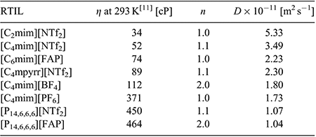
Peak-to-peak separations (ΔEp) for the first reduction peak are reported in Table 1, and are found to vary between 85 and 112 mV in the different RTILs. These values are relatively similar to that reported for the ferrocene/ferrocenium redox couple (84 to 98 mV) on the same electrode in the same RTILs.[24] This suggests that the kinetics of the electrochemical step are relatively fast and comparable to ferrocene/ferrocenium – this will also be explored in more detail in the digital simulation study. The second reduction process (peak 2) appears to show less chemical reversibility compared with the first reduction peak, which makes the measurement of peak-to-peak separations difficult. In some of the RTILs (especially [C2mim][NTf2] and [C4mim][NTf2]), the current is visibly larger for the second peak, which can be an indication of a higher electron count for the second step compared with the first step. The only RTIL that shows ideal chemically reversible behaviour for peak 2 is [C4mpyrr][NTf2], which is unsurprising, given the more chemically stable nature of the pyrrolidinium cation compared with the imidazolium and phosphonium cations, both of which have been known to deprotonate in the presence of highly basic species.[31,32] As shown in Table 1, the peak potential (E) for peak 1, and the separation of peaks 1 and 2 (Ep1 – Ep2), are relatively similar in the imidazolium RTILs, but occur at more negative potentials in RTILs with [FAP]− anions or [P14,6,6,6]+ cations. This suggests a stronger solvation of the DNT radical anion in imidazolium RTILs, which was also noted for the radical anion of TNT in RTILs.[24]
Square wave voltammetry (SWV) in the eight RTILs is also shown in the insets to Fig. 2, revealing two well defined and sharp peaks in all RTILs. There are small shoulders present on the first reduction peak in the RTILs [C4mim][BF4] and [C4mim][PF6], consistent with the split-wave feature observed in the CVs. Overall, the peaks are much sharper and well defined for SWV compared with CV, due to the method of sampling for SWV, which minimises non-Faradaic contributions. The baseline currents for the SWVs are relatively small and flat, except in the case of [C4mim][BF4] where a sloping baseline is observed. The extraction of current from SWV is very quick and simple, since peak 1 is well separated from peak 2 and non-Faradaic currents are negligible. In addition, the currents are generally higher for SWV compared with CV (see Table 1), although it is noted that the ratio (ISWV/ICV) varies in the different RTILs. These observations suggest that SWV may be the method of choice for the detection of DNT, particularly at lower concentrations. We note that this method has already been used by other groups for the sensing of low concentrations of DNT in RTILs.[19,20,33]
In order to calculate electron counts and diffusion coefficients for DNT, potential-step chronoamperometry was carried out on the first peak. The potential was stepped from a position where no Faradaic processes occur, to a potential after the first reduction peak (but before the onset of the second reduction peak). The experimental transient was analysed using the Shoup and Szabo expression,[23] allowing the extraction of values for nc (number of electrons multiplied by concentration) and D (diffusion coefficient), as shown in Table 2, noting that nc was divided by the concentration to obtain a value for n. It is clear that the electron count (n) is close to 1 in most RTILs, except in the two RTILs [C4mim][BF4] and [P14,6,6,6][FAP], which show a 2 electron count. This is consistent with a loss of the oxidation peak observed in the CVs of these two RTILs (Fig. 2e, h), and suggests that additional reduction processes are occurring. An electron count of 1 in most RTILs is comparable to that for TNT reduction,[24] suggesting that only one electron is added to one of the nitro groups during the first peak. This is also consistent with the behaviour observed for dinitroaromatics in conventional organic solvents.[7,8,10] The electron count for the second peak is much harder to deduce, but is likely to be larger than one in most RTILs due to the larger currents and less reversible shapes of the voltammograms for peak 2 observed in Fig. 2, suggesting that follow-up chemistry is occurring.
|
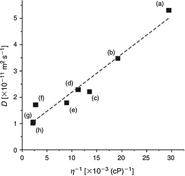
Fitting the chronoamperometric transients to the Shoup and Szabo expression[23] also gives values for the diffusion coefficient (D) for DNT in the RTILs, as shown in Table 2. D is observed to vary between ~1 × 10⁻¹¹ and 5 × 10⁻¹¹ m2 s−1, and decreases systematically as the viscosity of the RTIL increases. Fig. 3 shows a plot of the diffusion coefficient (D) versus the inverse of viscosity (η−1) for the eight RTILs (black squares), along with the line of best fit. An approximately linear relationship is observed, suggesting that DNT is diffusing ideally through the solvent. The values of D for DNT are slightly faster than those reported for TNT[24] in the eight RTILs, consistent with DNT being a slightly smaller molecule than TNT (with one less nitro group), and hence, able to diffuse more quickly through the solvent medium.
|
Digital Simulation Study of DNT Reduction in [P14,6,6,6][NTf2]
[P14,6,6,6][NTf2] was chosen as the most ideal RTIL to study the mechanism for 2,4-DNT reduction using digital simulation. This was because: i) it had a well defined and reversible one-electron reduction for peak 1, and ii) it is highly hydrophobic and showed excellent results for the detection of TNT directly in water samples in our previous work.[34] The electrode used for these experiments was a thin-film electrode (TFE), since a much smaller volume is required for the TFE (3 μL) compared with the microelectrode (20 μL), allowing for the use of significantly less stock-solution volume for the study of higher concentrations.
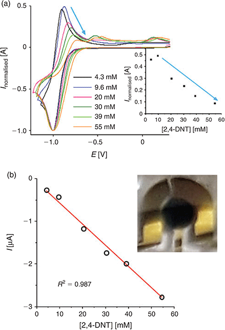
Fig. 4a shows experimental CVs for peak 1 of DNT at a range of concentrations from 4.3–55 mM. The reduction peak current is normalized to a nominal value of 1, and the potentials have arbitrarily been shifted to −1.0 V due to the use of the unstable reference electrode. The absolute currents for the oxidative back-peak were plotted against the concentration of DNT, as shown in the inset to Fig. 4a. It can be seen that the height of the back-peak decreases at concentrations above 9.6 mM; the normalized currents fall almost to zero, indicating that the electrogenerated radical anion is no longer present on the voltammetric timescale at these concentrations. This is an indication of a possible dimerisation reaction, similar to what was reported for TNT reduction in RTILs.[24] It is noted that similar behaviour was observed in other ionic liquids tested ([C4mim][NTf2] and [C4mim][PF6], results not shown), suggesting that the mechanism is likely to be the same in all RTILs.
|
A plot of the absolute current for peak 1 versus concentration is shown in Fig. 4b. In the concentration range studied, a linear relationship between current and concentration was observed (R2 = 0.987), with a gradient of the line of best fit (sensitivity) of 49.6 nA mM−1. It is obvious from the voltammetry that much lower concentrations can be studied and can be well distinguished from the background – this will be undertaken in our future work. The inset to Fig. 4b shows a photograph of the working, counter, and reference electrodes of the TFE covered with the RTIL, after three CV scans in the presence of 30 mM DNT. A very obvious blue precipitate accumulates on the working electrode at these concentrations. This product is more obvious on the TFE compared with the microdisk electrode, due to the much larger size of the working electrode, and hence substantially more of the reduction products are generated. A blue coloured precipitate has been observed previously by Olson et al.[35] in organic solvents and was attributed to the deprotonated DNT molecule. The blue precipitate is also visible at the lowest concentrations studied, although several more CV scans (>10) are required to observe this product. These observations suggest that an additional chemical reaction may also take place, alongside the dimerisation step.
It is noted here that some fouling/passivation of the electrode was observed in the CV currents after repetitive scans over peak 1. The effect was more severe at higher concentrations, and not recoverable even after waiting for more than 1 h, hinting at the possibility of a build-up of the electrogenerated products blocking the electrode surface. It is unlikely to be due to the depletion of analyte, since the charge under peak 1 at the lowest concentration was 1.04 × 10⁻¹⁰ C, equating to ~1 × 10⁻¹⁵ moles of DNT consumed (1 C = 1.04 × 10⁻⁵ moles), which is much lower than the ~9 × 10⁻⁹ moles of DNT available in a typical 3 μL aliquot. Therefore, only CVs from the first scan were used for the digital simulation study.
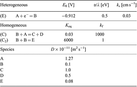
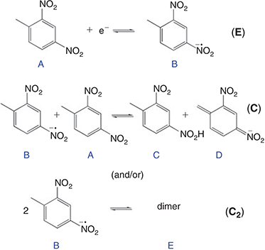
In order to provide further insight into the reaction mechanism, the digital simulation program DigiElch 8.0[26] was used to simulate the experimental voltammograms. Fig. 5 shows the experimental data (solid lines) and the ‘best fit’ fitted theoretical data (circles) obtained from simulation, for four chosen concentrations of DNT. The value of concentration and diffusion coefficient was fixed from the results in Table 2, and α/λ was fixed at 0.5 for simplicity, and all other parameters were varied systematically to obtain a reasonable fit to the experimental data. A range of mechanisms was input into the simulation program, starting from a simple one-electron reduction of DNT, and adding subsequent follow-up chemical steps. No further electrochemical steps were added, since the results from chronoamperometry revealed that only a one electron transfer occurs in this RTIL. The follow-up chemical steps that were added were: i) a proton abstraction of a parent DNT molecule by an electrogenerated radical anion (B + A = C + D) and ii) a dimerisation of the electrogenerated radical anion (B + B = E). Attempts to simulate without either of the two chemical steps did not arrive anywhere close to a reasonable fit, suggesting that both mechanisms likely take place. This is not unreasonable, since both mechanisms have previously been suggested to take place for 2,4-DNT or other dinitroaromatics in organic solvents.[8,10,36,37]
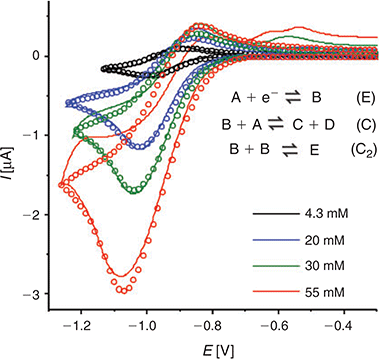
|
A heterogeneous rate constant (ks) of 0.03 cm−1 gave the best fit to the experimental data. This is the same order of magnitude reported previously for ferrocene,[38] TNT,[24] and mono-nitroaromatics[39] in RTILs, and is consistent with a relatively fast electron transfer step, as indicated by the peak-to-peak separation of peak 1. In the simulation, an uncompensated resistance (Ru) of 20 kΩ and double layer capacitance (Cdl) of 2 × 10⁻⁷ F were also included to further improve the fit of the CVs, and account for the background (non-Faradaic) currents. Fig. 5 shows the experimental and simulated CVs at four selected concentrations. The experimental data fits reasonably well with the simulation over the >10 times concentration range, and these fitting parameters are summarised in Table 3. The slightly lower experimental current observed at the highest concentration (55 mM), plausibly the result of the fouling/passivation of the working electrode surface, becomes obvious at these higher concentrations. On the reverse scan, additional anodic features are observed in the experimental data, likely to be due to oxidations of electrogenerated reduction products, but these were not included in the simulation for simplicity.
|
Based on the results from the digital simulation fitting parameters, this therefore leads us to propose a mechanism for DNT reduction in the RTIL [P14,6,6,6][NTf2], as shown in Fig. 6. A one-electron reduction of the DNT to the radical anion first occurs (E step). At sufficiently high concentrations, this radical anion can either abstract a proton from another parent DNT molecule (C step), or can dimerise (C2 step). This is believed to be the most likely mechanism that leads to the voltammetry observed in Fig. 5. The limiting parameters from the simulation are: i) the equilibrium constant (Keq) of the proton extraction step B + A = C + D, and ii) the forward rate constant (kf) for the dimerisation step B + B = E.
|
Conclusions
The reduction of 2,4-DNT has been studied in detail in eight RTILs. Two reduction peaks are observed in all RTILs, corresponding to the reduction of the two nitro groups on the aromatic ring. Chronoamperometry revealed that the electron count is 1 for most RTILs. However, an electron count of 2, combined with irreversible voltammetry for peak 1, in two of the RTILs ([C4mim][BF4] and [P14,6,6,6][FAP]) suggest that the radical anion is unstable, and that further reductions occur. DNT diffuses ideally through the RTIL media, as indicated by the linear relationship between diffusion coefficient and the inverse of viscosity. In the RTIL [P14,6,6,6][NTf2], a digital simulation study was carried out over a range of concentrations. The best fit to experimental data suggests that the electrogenerated radical anion can either deprotonate a parent DNT molecule, or can dimerise with another radical. Both mechanisms likely occur on the timescale of the voltammetric experiment. Finally, square wave voltammetry appears to be a better method compared with cyclic voltammetry for the detection of DNT in RTILs, due to the clear separation of the first reduction peak from any subsequent reduction processes.
Conflicts of Interest
The authors declare no conflicts of interest.
Acknowledgements
The authors thank Professor Chris Hardacre for the kind donation of one of the RTILs used in this work. DSS thanks the Australian Research Council for a Future Fellowship (FT170100315).
References
[1] R. J. Harper, J. R. Almirall, K. G. Furton, Talanta 2005, 67, 313.| Crossref | GoogleScholarGoogle Scholar |
[2] United States Environmental Protection Agency, Technical Fact Sheet – Dinitrotoluene (DNT), January 2014, EPA 505-F-14-010.
[3] J. Wang, Electroanalysis 2007, 19, 415.
| Crossref | GoogleScholarGoogle Scholar |
[4] H. A. Yu, D. A. DeTata, S. W. Lewis, D. S. Silvester, Trends Analyt. Chem. 2017, 97, 374.
| Crossref | GoogleScholarGoogle Scholar |
[5] S. Singh, J. Hazard. Mater. 2007, 144, 15.
| Crossref | GoogleScholarGoogle Scholar |
[6] F. Akhgari, H. Fattahi, Y. M. Oskoei, Sens. Actuators B Chem. 2015, 221, 867.
| Crossref | GoogleScholarGoogle Scholar |
[7] A. S. Mendkovich, M. A. Syroeshkin, L. V. Mikhalchenko, M. N. Mikhailov, A. I. Rusakov, V. P. Gul’tyai, Int. J. Electrochem. 2011, 2011,
| Crossref | GoogleScholarGoogle Scholar |
[8] E. J. Olson, W. C. Isley, J. E. Brennan, C. J. Cramer, P. Bühlmann, J. Phys. Chem. C 2015, 119, 13088.
| Crossref | GoogleScholarGoogle Scholar |
[9] K. Bratin, P. T. Kissinger, R. C. Briner, C. S. Bruntlett, Anal. Chim. Acta 1981, 130, 295.
| Crossref | GoogleScholarGoogle Scholar |
[10] N. A. Macías-Ruvalcaba, J. P. Telo, D. H. Evans, J. Electroanal. Chem. 2007, 600, 294.
| Crossref | GoogleScholarGoogle Scholar |
[11] L. E. Barrosse-Antle, A. M. Bond, R. G. Compton, A. M. O’Mahony, E. I. Rogers, D. S. Silvester, Chem. Asian J. 2010, 5, 202.
| Crossref | GoogleScholarGoogle Scholar |
[12] M. C. Buzzeo, R. G. Evans, R. G. Compton, ChemPhysChem 2004, 5, 1106.
| Crossref | GoogleScholarGoogle Scholar |
[13] D. S. Silvester, R. G. Compton, Z. Phys. Chem. 2006, 220, 1247.
| Crossref | GoogleScholarGoogle Scholar |
[14] M. J. A. Shiddiky, A. A. J. Torriero, Biosens. Bioelectron. 2011, 26, 1775.
| Crossref | GoogleScholarGoogle Scholar |
[15] N. V. Shvedene, D. V. Chernyshov, I. V. Pletnev, Russ. J. Gen. Chem. 2008, 52, 80.
[16] D. S. Silvester, Analyst (Lond.) 2011, 136, 4871.
| Crossref | GoogleScholarGoogle Scholar |
[17] D. S. Silvester, L. Aldous, in Electrochemical Strategies in Detection Science (Ed. D. W. M. Arrigan) 2016, pp. 341–385 (RSC: Cambridge, UK).
[18] W. Wei, A. Ivaska, Anal. Chim. Acta 2008, 607, 126.
| Crossref | GoogleScholarGoogle Scholar |
[19] A. J. Bandodkar, A. M. O’Mahony, J. Ramirez, I. A. Samek, S. M. Anderson, J. R. Windmiller, J. Wang, Analyst 2013, 138, 5288.
| Crossref | GoogleScholarGoogle Scholar |
[20] C. Xiao, A. Rehman, X. Zeng, Anal. Chem. 2012, 84, 1416.
| Crossref | GoogleScholarGoogle Scholar |
[21] M. Sharp, Electrochim. Acta 1983, 28, 301.
| Crossref | GoogleScholarGoogle Scholar |
[22] D. S. Silvester, A. J. Wain, L. Aldous, C. Hardacre, R. G. Compton, J. Electroanal. Chem. 2006, 596, 131.
| Crossref | GoogleScholarGoogle Scholar |
[23] D. Shoup, A. Szabo, J. Electroanal. Chem. Interfacial Electrochem. 1982, 140, 237.
| Crossref | GoogleScholarGoogle Scholar |
[24] C. Kang, J. Lee, D. S. Silvester, J. Phys. Chem. C 2016, 120, 10997.
| Crossref | GoogleScholarGoogle Scholar |
[25] J. Lee, K. Murugappan, D. W. M. Arrigan, D. S. Silvester, Electrochim. Acta 2013, 101, 158.
| Crossref | GoogleScholarGoogle Scholar |
[26] DigiElch Electrochemical Simulation Software 2018 (Gamry Instruments: Warminster, PA). Available at: https://www.gamry.com/digielch-electrochemical-simulation-software/ (accessed 28 June 2018).
[27] R. G. Compton, C. E. Banks, Understanding Voltammetry 2007 (World Scientific: Singapore).
[28] E. I. Rogers, D. S. Silvester, D. L. Poole, L. Aldous, C. Hardacre, R. G. Compton, J. Phys. Chem. C 2008, 112, 2729.
| Crossref | GoogleScholarGoogle Scholar |
[29] D. S. Silvester, S. Uprety, P. J. Wright, M. Massi, S. Stagni, S. Muzzioli, J. Phys. Chem. C 2012, 116, 7327.
| Crossref | GoogleScholarGoogle Scholar |
[30] A. M. O’Mahony, D. S. Silvester, L. Aldous, C. Hardacre, R. G. Compton, J. Chem. Eng. Data 2008, 53, 2884.
| Crossref | GoogleScholarGoogle Scholar |
[31] R. G. Evans, O. V. Klymenko, S. A. Saddoughi, C. Hardacre, R. G. Compton, J. Phys. Chem. B 2004, 108, 7878.
| Crossref | GoogleScholarGoogle Scholar |
[32] E. I. Izgorodina, R. Maganti, V. Armel, P. M. Dean, J. M. Pringle, K. R. Seddon, D. R. MacFarlane, J. Phys. Chem. B 2011, 115, 14688.
| Crossref | GoogleScholarGoogle Scholar |
[33] L. Yu, Y. Huang, X. Jin, A. J. Mason, X. Zeng, Sens. Actuators B 2009, 140, 363.
| Crossref | GoogleScholarGoogle Scholar |
[34] H. A. Yu, J. Lee, S. W. Lewis, D. S. Silvester, Anal. Chem. 2017, 89, 4729.
| Crossref | GoogleScholarGoogle Scholar |
[35] E. J. Olson, T. T. Xiong, C. J. Cramer, P. Bühlmann, J. Am. Chem. Soc. 2011, 133, 12858.
| Crossref | GoogleScholarGoogle Scholar |
[36] I. Gallardo, G. Guirado, J. Marquet, N. Vilà, Angew. Chem. Int. Ed. 2007, 46, 1321.
| Crossref | GoogleScholarGoogle Scholar |
[37] I. Gallardo, G. Guirado, Phys. Chem. Chem. Phys. 2008, 10, 4456.
| Crossref | GoogleScholarGoogle Scholar |
[38] N. Fietkau, A. D. Clegg, R. G. Evans, C. Villagran, C. Hardacre, R. G. Compton, ChemPhysChem 2006, 7, 1041.
| Crossref | GoogleScholarGoogle Scholar |
[39] C. Lagrost, L. Preda, E. Volanschi, P. Hapiot, J. Electroanal. Chem. 2005, 585, 1.
| Crossref | GoogleScholarGoogle Scholar |
* Debbie S. Silvester was awarded the 2017 Peter W. Alexander Medal from the Analytical & Environmental Division of the RACI.