Firebrand burning under wind: an experimental study
Weidong Yan A B , Naian Liu A B * , Hong Zhu A B * , Haixiang Chen
  A B , Xiaodong Xie A B , Wei Gao
  A B and Zhihao Du A B
A
B
Abstract
Spot fires play a significant role in the rapid spread of wildland and wildland–urban interface fires.
This paper presents an experimental and modelling study on the flaming and smouldering burning of wood firebrands under forced convection.
The firebrand burning experiments were conducted with different wind speeds and firebrand sizes.
The burning rate of firebrands under forced convection is quantified by wood pyrolysis rate, char oxidation rate and a convective term. The firebrand projected area is correlated with firebrand diameter, char density, wind speed, and flaming or smouldering burning. A surface temperature model is derived in terms of condensed-phase energy conservation. We finally establish a simplified firebrand transport model based on the burning rate, projected area and surface temperature of firebrands.
The mass loss due to wood pyrolysis is much greater than that due to char oxidation in self-sustaining burning. The burning rate is proportional to U1/2, where U is wind speed. The projected area for flaming firebrands decreases more rapidly than that for smouldering ones. The firebrand surface temperature is mainly determined by radiation.
Knowledge about firebrand burning characteristics is essential for predicting the flight distance and trajectory in firebrand transport.
Keywords: burning rate, firebrand density, firebrands, flaming and smouldering, forced convection, projected area, surface temperature, transport trajectory.
Introduction
Spot fire denotes the phenomenon that firebrands (e.g., burning barks and twigs) are lofted by the buoyancy of the flame plume, and may be carried by the wind. Firebrands can be transported for hundreds or even tens of thousands of metres by wind (Hall et al. 2015). Spot fire may form continuous showers (Fernandez-Pello 2017), and normally cause numerous new ignitions beyond the primary burning zone (Tarifa et al. 1965; Manzello et al. 2020). Spot fire plays a significant role in the rapid spread of wildland and wildland–urban interface (WUI) fires (Suzuki et al. 2015; Manzello 2020) and poses a severe risk of igniting large areas of wildland fuels and even WUI buildings (Sardoy et al. 2007; Song et al. 2017; Santoso et al. 2019). At least 50% of ignitions are attributable to firebrands in WUI areas (Mell et al. 2010; Fang et al. 2021).
During the past several decades, there has been much attention on firebrand generation, transport and ignition (for more details, refer to the comprehensive reviews by Manzello et al. (2020) and Wadhwani et al. (2022)). Prediction of the flight distance and trajectory of self-sustained burning firebrands highly depends on understanding firebrand burning. However, despite considerable research on firebrand transport, the firebrand burning mechanism under wind (forced convection) is still poorly understood. Most relevant studies fall into empirical modelling or experimental analysis. Tarifa et al. (1965) pioneered wind tunnel experiments on spherical and cylindrical firebrand transport and developed empirical models to discuss the influence of firebrand size, density, type and moisture on transport trajectories. Some studies investigated the trajectories of firebrands initially elevated from fire plumes by theoretical calculations (Lee and Hellman 1969; Woycheese et al. 1999) or numerical simulations (Anthenien et al. 2006; Oliveira et al. 2014). Albini 1983 developed an empirical burning rate model for transporting firebrands in wind-driven fires by line thermals. Himoto and Tanaka (2005) proposed a model for wind-driven firebrands without considering firebrand burning. Ellis (2013) measured the duration of flaming burning (flameout time), total burning time during flight (burnout time) and mass at burnout of 192 samples in a CSIRO blower-type vertical wind tunnel (Knight 2001). However, the burning mechanism of firebrands was not discussed. Almeida et al. (2011) also established an empirical mass model for flaming and smouldering firebrands with a vertical wind tunnel at different speeds.
Very limited research has touched on the firebrand burning mechanism under forced convection through experimental and theoretical analyses. Mukunda et al. (1985) conducted burning experiments on wooden spheres under natural convection and developed a wood burning model, showing mass loss and diameter reduction with increasing initial diameter of firebrand samples. They predicted the burning time, mass, diameter, surface temperature and core temperature of firebrands. Song et al. (2017) analysed the flight distance and mass change of firebrands experimentally. However, firebrand burning was not fully self-sustaining, and the experimental transport range was limited. Urban et al. (2019a) provided a method to measure the surface temperature of firebrands, but did not correlate the surface temperature with the firebrand burning rate.
Moreover, firebrands under forced convection may be in a mode of flaming or smouldering burning. However, burning modes have rarely been distinguished in evaluating firebrand burning rate and size. During firebrand burning, the pyrolysis front propagates inward and forms char gradually. When wood pyrolysis is complete, the inhibitory effect of pyrolysis gas on oxygen diffusion is weakened, allowing more oxygen to diffuse to the firebrand surface. As firebrand temperature increases, char oxidation occurs (Sardoy et al. 2006) on the surface rather than through the whole sample (Sardoy et al. 2007). Tse and Fernandez-Pello (1998) suggested that volume reduction may be attributed to char oxidation on the particle surface. Based on liquid fuel burning theory (Spalding 1953; Turns 2000), the mass transfer number B is an important parameter affecting the burning rate of firebrands (Pagni 1981; Turns 2000; Lattimer et al. 2022). Woycheese and Pagni (1999) determined the maximum propagation distance of combusting firebrands exposed to the fire plume and constant horizontal wind, without considering the mode of flaming or smouldering burning. Lattimer et al. (2022) used analytical equations to evaluate firebrand temperature, mass loss rate, char diameter and burning duration based on char oxidation. However, wood pyrolysis was neglected.
Considering the above problems, this work studies the flaming and smouldering burning of wood firebrands under forced convection by experimental and modelling approaches. Firebrand density, burning rate, projected area and surface temperature are analysed. Correlations for firebrand burning characteristics are developed and used in a firebrand transport model.
Experimental methods
Sample
Reflective of the firebrand shape and size observed in WUI fires and typically used in experimental studies (Xiong et al. 2020; Manzello et al. 2020), spherical wooden firebrands (Schima Superba) with diameters of 10, 15, 20 and 25 mm were used as the samples in the present work. The sphere has been regarded as a typical shape for firebrand research (Wadhwani et al. 2022; Dal-Ri dos Santos and Yaghoobian 2023) because natural firebrands sometimes undergo a gradual transition into near-spheroids through burning (Urban et al. 2019b). Moreover, the burning model and transport model for spherical wooden firebrands can be extended for cylinder firebrands by simple geometric transformation (Lattimer et al. 2022). Before the experiments, the samples were dried in a drying oven (Jinghong electric heating blast drying oven, XMTD-8222) at 100–120°C for 24 h (Mukunda et al. 1985) and were then stored in a sealed bag. After drying, the moisture contents of the samples were 0.73–1.56%. The densities of the oven-dry samples were 0.520–0.599 g cm−3. The sample masses were 0.267–4.705 g, with a relative standard deviation <5%.
Experiment
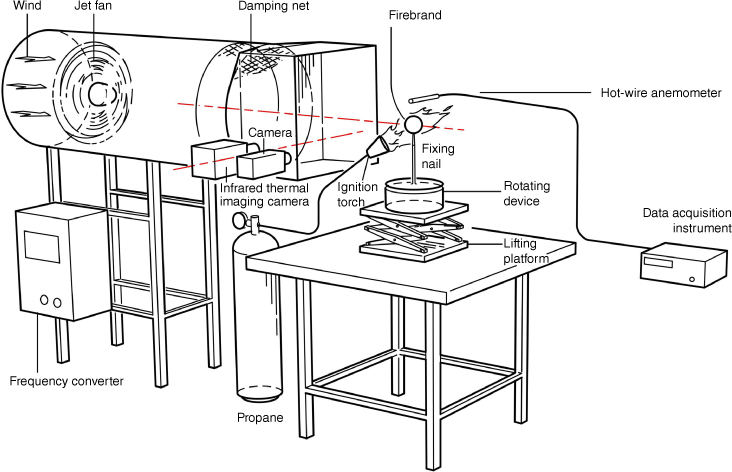
The experimental set-up is illustrated in Fig. 1. A jet fan (Suitai, China, model SDS4.0-2.2kw-2p), equipped with two layers of damping nets inside the outlet end, provided a stable airflow. The wind speed was adjusted through a frequency converter. A hot-wire anemometer (Kanomax, CTA/HWA7000) was placed 5 cm above the centreline of the firebrand to measure the wind speed. The wind speeds varied between 0 and 8 m s−1 with a fluctuation of ±5%. A digital video camera (Sony FDR-AX60, 50 frames s−1, 1920 × 1080 pixels) and an infrared thermal imaging camera (American FLIR T650sc, 30 frames s−1, 640 × 480 pixels) recorded firebrand burning and surface temperature from the front view. Firebrands were ignited by a propane igniter, which was turned off immediately when the firebrands reached self-sustaining burning. Self-sustaining burning means that after the igniter is removed, the firebrand continues to burn until firebrand breakage occurs. Under the same experimental conditions, the ignition times are identical. Burned mass was measured with an electronic balance (Jingfei Instrument Technology, DHS-10A, resolution 0.005 g) after the sample was quenched with water and then dried. As a stationary firebrand burns fast on the windward side and slowly on the leeward side, the firebrand in each test of this work was rotated on a fixing nail at a speed of 5 s per circle for uniform burning. The rotating samples under forced convection are close to the conditions of natural firebrands under wind (Manzello et al. 2020). Burning tests of rotational and non-rotational firebrands under natural convection showed comparable temporal variations of firebrand masses. Therefore, the speed relative to air caused by rotating (calculated to be lower than 0.0126 m s−1) is ignored in this work.
We quenched the firebrand for each set of experimental conditions at approximately 20 different moments and measured the instantaneous features such as sample mass and projected area. The quenched firebrands were dried to a moisture content of 2.21–3.76%. For each set of experimental conditions, a large number of repeated tests were performed before the experiment to obtain the burning duration of firebrands. Then, the entire burning duration was divided into ~20 instants for firebrand quenching. This step is consistent with Mukunda et al. (1985). The electronic balance was utilised for larger firebrand masses (>12.95 g (Almeida et al. 2011)) or lower wind speeds (<2 m s−1 (Lattimer et al. 2022)) without quenching the firebrand. However, the sample masses (<4.70 g) and wind speeds (>2 m s−1) in the present study, in accord with those of firebrands in natural fires (Hall et al. 2015; Storey et al. 2020b), caused unacceptable fluctuation in pre-experiments without quenching. The firebrand surface temperature was measured by an infrared thermal imaging camera, calibrated using a thermocouple contacting the surface of non-rotating firebrands. An emissivity of 0.9 (Sardoy et al. 2007; Lattimer et al. 2022) was adopted for the same temperature as the thermocouple. The firebrand image recorded by a digital video camera was converted to a greyscale image and then into a binary image by setting a cut-off threshold. The projected area of the firebrand was calculated with pixels and a reference scale, and then the firebrand diameter was obtained. Each experiment was repeated at least four times.
Model description
At low wind speeds, the firebrand is first flaming and then smouldering. At high wind speeds, the firebrand is always smouldering. The mass and volume of a firebrand during burning decrease with burning time. At low wind speeds, the firebrand density decreases monotonically with burning time during flaming, whereas it does not change significantly during smouldering.
Flaming and smouldering firebrands involve different char oxidation mechanisms, with the main products being CO and CO2. The firebrands in this work are assumed to be homogeneous wood. A mechanism of firebrand burning (consisting of wood pyrolysis and char oxidation) is proposed, and the ratio of wood pyrolysis rate to char oxidation rate is determined. A burning rate model incorporating the wood pyrolysis rate, char oxidation rate and a convective term is developed. Based on mass conservation, the reduction rate of the firebrand projected area is evaluated from the char oxidation rate under forced convection. The firebrand surface temperature is derived in terms of condensed-phase energy conservation. The surface temperature of the firebrand is mainly determined by radiation, and the relationship between surface temperature and wind speed is then obtained. Finally, based on the above, and in combination with the principles of mechanics, a firebrand transport model is developed to calculate the transport trajectory and essential parameters affecting the burning of firebrands.
Results and discussion
Experimental observations
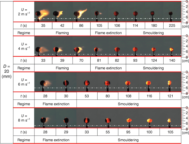
Fig. 2 shows the burning phenomena of a firebrand with a diameter of 20 mm under different wind speeds. The dotted white lines denote the specific position of the fixing nail. For each wind speed, the first image corresponds to the moment when the propane igniter was just turned off, and the last image of the smouldering stage corresponds to firebrand breakage. As observed, the firebrands first burned with a flame, and after the flame was extinguished, residue smouldering continued at wind speeds of 2 and 4 m s−1. The flame was extinguished quickly and then residue smouldering continued at wind speeds of 6 and 8 m s−1.
The firebrand burning results in a reduction in mass and size, as well as eventual breakage along the wood grain. The firebrand breaks off and forms multiple smaller firebrands that are blown away by the wind. The higher the wind speed, the shorter the firebrand breakage time. The breakage of the firebrand significantly promotes mass and heat transfer and reduces the firebrand mass. Although firebrand burning was suggested to be affected by firebrand breakage (Thunman et al. 2002; Kuo and Hwang 2003; Almeida et al. 2011) and ash formation (Hall et al. 2015), we do not consider these effects in this work because firebrand breakage occurred only in the last few seconds and the ash accumulated only at the wind speed of 2 m s−1 during char oxidation. Additionally, the thin ash layer (Fig. 2) is considered to have a minor effect on surface energy transfer and gas diffusion (Wong et al. 2022).
Firebrand density and burning mechanism
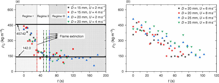
The temporal variation of firebrand density under different wind speeds and particle diameters is shown in Fig. 3. In Fig. 3a, under wind speeds of 2 and 4 m s−1, Regimes I–III correspond to the flaming stage, flame extinction and the smouldering stage, respectively. The dotted lines denote the time of flame extinction.
Mukunda et al. (1985) carried out a combustion experiment on spheroid wood particles with different diameters under natural convection. Experimental results showed that the diameter squared decreases by 20–25%, and the particle mass decreases by 75–80% during flaming. The mass loss of a firebrand is caused by pyrolysis and char oxidation, while the volume loss is mainly attributable to char oxidation (Tse and Fernandez-Pello 1998; Porteiro et al. 2007). The firebrand density decreases in flaming (Regime I) owing to wood pyrolysis and char oxidation. The firebrand density almost remains constant in smouldering (Regime III), in which char oxidation is the primary reaction. Char oxidation can exist with flaming here because the flame cannot fully cover the firebrand surface. Thus, the reduction in firebrand density is considered mainly attributable to wood pyrolysis. Pyrolysis and char oxidation occur simultaneously during flaming. The squared diameter loss is ~25%, density loss is ~70%, and mass loss is ~80%, of which pyrolysis accounts for ~69%. The experimental results are consistent with those of Mukunda et al. (1985). In Fig. 3b, smouldering firebrand density decreases under wind speeds of 6 and 8 m s−1, which differs from the almost constant firebrand density in the smouldering stage under 2 and 4 m s−1 (Regime III in Fig. 3a). This difference may be attributable to the fact that the smouldering firebrand under lower wind speeds is dominated by char oxidation, and under higher wind speeds, undergoes pyrolysis and char oxidation simultaneously.
The volatiles released from wood pyrolysis support flaming combustion. Wood char normally contains small amounts of oxygen, hydrogen and nitrogen, which can be neglected. Thus, char is assumed to be made of pure carbon (Porteiro et al. 2007). The flame then affects the char oxidation reaction. Porteiro et al. (2007) assumed that char oxidation occurring in flaming and smouldering firebrands results in the simultaneous generation of CO and CO2. However, the oxygen diffuses to the firebrand surface with difficulty in flaming burning, whereas it directly contacts the char surface in smouldering burning. Thus, for a flaming firebrand, CO2 and CO are generated on the flame and firebrand surfaces, respectively (Caram and Amundson 1977). For a smouldering firebrand, CO and CO2 are produced on the firebrand surface, and the overall rate of char consumption is calculated using Eqn 4 as the ratio between CO and CO2 Porteiro et al. (2007). The above considerations lead to the following firebrand burning mechanism:
where ζ is the stoichiometric coefficient, and η is the CO-to-CO2 ratio. The subscripts fla and smo denote flaming and smouldering stages, respectively. The temperature T (K) is 950–1150 K, and the corresponding η is 1.057–1.101. The η = 1.078 for a temperature of 1050 K is chosen, and the resulting error is negligible. ζfla = 1.333, and ζsmo = 2.474. For wind speeds of 2 and 4 m s−1, the flaming stages follow Eqns 1–3, and the smouldering stages follow Eqn 4. For wind speeds of 6 and 8 m s−1, the flaming stages are ignored, and the smouldering stages follow Eqns 1 and 4.
Burning rate
The burning rate (mass loss rate) of a firebrand is
where mfb is the firebrand mass (g), t the burning time (s), the char oxidation rate (g s−1), φpyr the ratio of wood pyrolysis rate to char oxidation rate, and the subscript pyr denotes wood pyrolysis.
For the flaming stages at 2 and 4 m s−1:
where is the mean ratio of wood pyrolysis rate to char oxidation rate in the burning stage, Ω the firebrand volume (m3), ρ the firebrand density (kg m−3). The subscript oxi denotes the char oxidation, 0 the initial value, and fe the flame extinction.
For the smouldering stages at 2 and 4 m s−1:
For the smouldering stages at 6 and 8 m s−1:
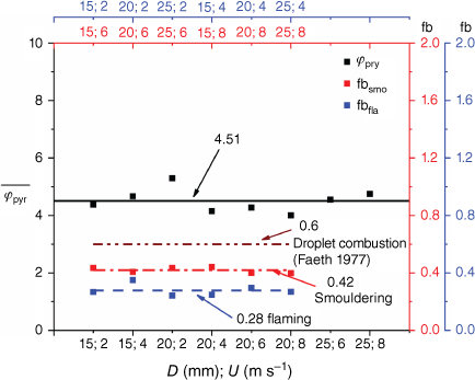
where the subscript bre denotes firebrand breakage. Table 1 presents firebrand density (ρ) and volume (Ω), where D is firebrand diameter (mm), and U is the wind speed (m s-1). The value is 4.51 for the flaming stages at 2 and 4 m s−1 and the smouldering stages at 6 and 8 m s−1, indicating mass loss due to wood pyrolysis is much greater than that caused by char oxidation, consistent with Zhu and Liu (2020).
| D (mm) | U (m s−1) | Ω × 10−7 (m3) | ρ A (kg m−3) | |||||||
|---|---|---|---|---|---|---|---|---|---|---|
| Ωfla,0 | Ωfla,fe | Ωsmo,0 | Ωbre | ρfla,0 | ρfla,fe | ρsmo,0 | ρbre | |||
| 15 | 2 | 14.3 | 7.0 | 8.7 | 7.0 | 457.4 | 142.0 | 142.0 | 142.0 | |
| 15 | 4 | 13.6 | 7.1 | 8.8 | 5.8 | 457.4 | 142.0 | 142.0 | 142.0 | |
| 20 | 2 | 34.0 | 19.8 | 22.8 | 6.0 | 457.4 | 142.0 | 142.0 | 142.0 | |
| 20 | 4 | 37.2 | 17.3 | 20.1 | 7.2 | 457.4 | 142.0 | 142.0 | 142.0 | |
| 20 | 6 | – | – | 36.9 | 17.7 | – | – | 457.4 | 142.0 | |
| 20 | 8 | – | – | 38.5 | 17.1 | – | – | 457.4 | 142.0 | |
| 25 | 6 | – | – | 73.3 | 37.5 | – | – | 457.4 | 142.0 | |
| 25 | 8 | – | – | 73.1 | 38.9 | – | – | 457.4 | 142.0 | |
The sample in this work is assumed to be homogeneous wood with uniform mass loss. The gas diffusivity Dm under air is 1.6 × 10⁻⁵ m2 s−1 for CO2 at 298 K and 2.08 × 10⁻⁵ m2 s−1 for CO at 293 K. Thermal diffusion α is 2.058 × 10⁻⁵ m2 s−1 for air at 300 K. Thus, the Lewis number Le = α/Dm ≈ 1 (Turns 2000; Lattimer et al. 2022). The power law relationship between the Nusselt (Nu) and Reynolds (Re) numbers has been fully studied for external flow (Incropera et al. 2007). They are correlated by a multiplicative correction of an additional convective term under forced convection for droplet combustion (Faeth 1977; Incropera et al. 2007):
where the Prandtl number Pr = 0.707 (Incropera et al. 2007; Lattimer et al. 2022). As the Pr value varies from 0.707 to 0.728 within 300–1200 K (Incropera et al. 2007; Lattimer et al. 2022), the temperature-induced error is within 3%. Re = D0ρgU/μ (Lattimer et al. 2022), where D0 is the initial firebrand diameter (mm), and the dynamic viscosity μ = 1.846 × 10⁻⁵ (N s m−2) (Incropera et al. 2007). The diameter-induced mean error in Re1/2 is ~5.5%.
Based on the char oxidation rate (, L is firebrand length (mm)) (Lattimer et al. 2022), the burning rate of spherical wooden firebrands under forced convection is formulated as
where the gas diffusion constant Dm = 1.84 × 10⁻⁵ m2 s−1 (Lattimer et al. 2022), and the air density ρg = 1.1614 kg m−3 at 300 K (Incropera et al. 2007). The mass transfer number and , where Y is the mass fraction . The firebrand diameter D (see Fig. 4) is obtained by linear fitting (Tarifa et al. 1965).
Here, the parameters βD and δD depend on wood type and moisture content.
where S is the projected area of the sample (mm2), and the parameters β = βDπ/4 and δ = δDπ/4. Thus, the burning rate depends on firebrand diameter, flaming or smouldering burning, pyrolysis rate and relative wind speed.
Firebrand diameter change under (a) 2 m s−1, (b) 4 m s−1, (c) 6 m s−1, and (d) 8 m s−1 wind speeds.
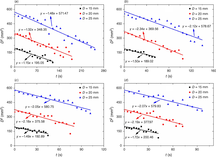
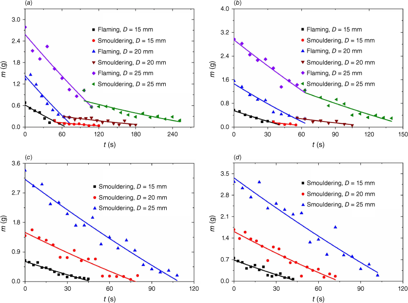
Then, only parameter fb is unknown in Eqn 14. The firebrand mass (Fig. 5) is introduced to solve for fb, and expressed as:
where m0 = Ωfla,0ρfla,0 or m0 = Ωsmo,0ρsmo,0 (Table 1). We substitute Eqn 14 (combined with Eqn 15) into Eqn 17, and integrate the expression. Then, the correction factor fb value (Fig. 6) is determined by non-linear fitting Eqn 17 in integral form with and different experimental mfb, m0 and D0 values. The trends of burned mass with quenching over burning time agree well with previous reports (Almeida et al. 2011; Lattimer et al. 2022) at wind speeds of 2 and 4 m s−1. Spherical wooden firebrand burning, involving wood pyrolysis and char oxidation, significantly differs from droplet combustion in heat and mass transfer processes. Thus, the fb values for flaming and smouldering burning of wood firebrands obtained by the above regression analysis, rather than the empirical value of 0.6 concerning droplet combustion, are used for the following calculations.
Projected area
The variation of firebrand projected area is mainly attributable to char oxidation (Tse and Fernandez-Pello 1998; Porteiro et al. 2007). The char oxidation rate is:
The char mass is formulated as:
Based on the char oxidation rate from Eqns 14, 18, and 19, the reduction rate of the projected firebrand is:
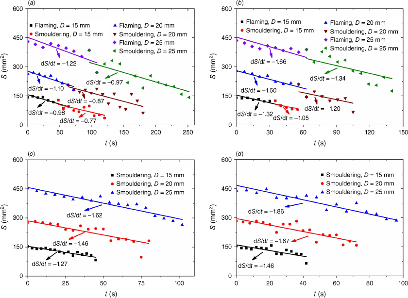
The theoretical dS/dt values for flaming and smouldering firebrands are indicated in Fig. 7, and agree with the experimental data. Based on Eqn 20,
A higher dS/dt value corresponds to a higher char density, a lower ln(1 + B), a lower firebrand diameter, or a lower wind speed. The ln(1 + B) value in flaming is much higher than that in smouldering. Thus, dS/dt in flaming is slightly lower than in smouldering under 2 and 4 m s−1 wind speeds in Fig. 7.
Surface temperature
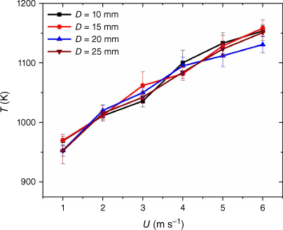
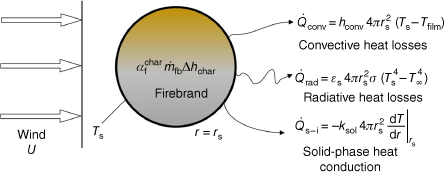
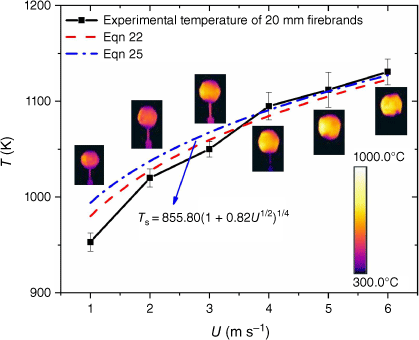
Fig. 8 shows the experimental firebrand surface temperature (extracted as the average value in the first 10 s) under forced convection. The higher the wind speed, the higher the surface temperature, indicating that the heat generated by firebrand burning exceeds the heat loss when the wind speed is increased. As presented in Fig. 9, the condensed-phase energy conservation at the firebrand surface is:
where Ts denotes the firebrand surface temperature, the mass fraction of char in firebrand , the heat of char oxidation Δhchar is 21.0 MJ kg−1 (Lattimer et al. 2022), and the thermal conductivity of the solid phase ksol is 0.1 W m−1 K−1 (Sardoy et al. 2006). The firebrand radius r = D/2 and the subscript s denotes the surface. The temperature of the gas phase film Tfilm = (Ts + T∞)/2 ≈ 700 K. The convective heat transfer coefficient hconv = Nukfilm/D, where the thermal conductivity of air kfilm is 5.24 × 10⁻² W m−1 K−1 at 700 K. The Stefan–Boltzmann constant is σ = 5.67 × 10⁻⁸ W m−2 K−4. The temperature T∞ = 293.15 K. The emissivity εs = 0.9 (Sardoy et al. 2007; Lattimer et al. 2022). It is reasonable to assume that the emissivity remains constant because the temperature values are measured in the first 10 s, during which the firebrand surface is always covered with char (Fig. 2). The temperature gradient at the firebrand surface (Turns 2000) is
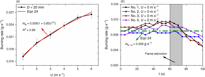
where the subscript nc denotes natural convection, and the specific heat capacity at constant pressure cp is 1075 J kg−1 K−1. The particle diameter varies insignificantly in 10 s and is assumed as a constant D0. Then, based on Eqn 14, satisfies
where K is the function coefficient. The larger the firebrand diameter and wind speed, the greater the firebrand burning rate. As illustrated in Fig. 10, the firebrand burning rate significantly depends on the wind speed. The K and values are obtained by fitting the experimental firebrand burning rate and Eqn 24. The reliability of Eqn 24 is verified by good agreement with experimental data under natural convection. Then, the firebrand surface temperature is calculated with Eqn 22. It is found that the firebrand surface temperature is mainly determined by radiation, with a contribution of more than 90%. because . Based on Eqns 22 and 24, the relation between firebrand surface temperature and wind speed is:
The experimental and calculated surface temperatures are in good agreement, as shown in Fig. 11. The surface temperature increases with wind speed, as the heat from the firebrand burning overcomes the heat loss.
Transport trajectory
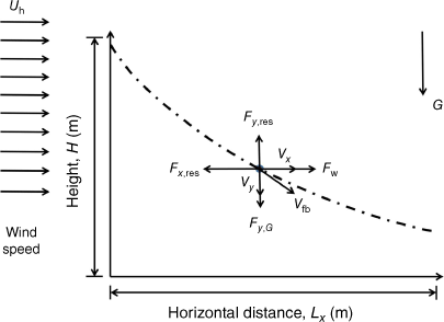
The firebrand trajectory is analysed with some assumptions: (1) firebrand uplift, rotation and vibration are neglected. (2) Firebrands do not affect each other. (3) Only the relative velocity of a firebrand and the surrounding air is considered during the firebrand transport. The firebrand transport model is presented in Fig. 12, where H is the height of the firebrand (m), Lx the horizontal transport distance (m), Uh the horizontal wind speed (m s−1), Vfb the firebrand velocity (m s−1), F the force (N), Fy,G = mg the force exerted by gravity on the firebrand, Fy,res the air resistance, Vx the horizontal speed of the firebrand, and Vy the vertical speed of the firebrand. The drag force of wind on the firebrands is equal to the air resistance in the horizontal direction (Fw = Fx,res). Based on Newton’s second law and discretisation technique,
where CD is the drag coefficient, subscript i denotes iteration and the relative velocity Ur,i≈||Vfbi − U||. Based on Eqns 14, 16, 20 and 25, , where , , , , , and Δt is the time step.
The height of firebrand and horizontal flight distance are:
The drag coefficient (Ganser 1993) is calculated by:
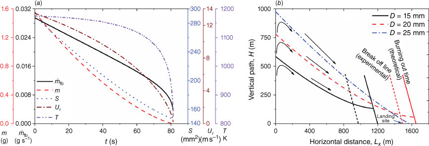
where K1 is Stokes’ shape factor, and K2 is Newton’s shape factor. Here, K1 = K2 = 1. The transport trajectory is calculated for firebrands of D = 15, 20 and 25 mm in self-sustaining burning. The initial values of the mass (Eqn 17, Fig. 5) and the projected area (Eqn 20, Fig. 7) are the mean values at t = 0 s under 6 and 8 m s−1 wind speeds. Both β and δ are evaluated based on the slopes for 6 and 8 m s−1 in Fig. 7. The ambient wind speed is set as 20 m s−1. The theoretical maximum height of firebrands in self-sustaining burning (Albini 1979) is:
Fig. 13 illustrates the calculated results of the transport model. The burning rate, projected area, relative velocity between firebrands and the surrounding fluid, and firebrand surface temperature are presented in Fig. 13a. The calculated firebrand flight trajectory is indicated in Fig. 13b. The wind speed and transport distance correspond with those in wildfires (Storey et al. 2020a, 2020b). As shown, firebrands with diameters of 15 and 20 mm burned out before landing, whereas the firebrand with a diameter of 25 mm remained burning on landing. The calculated descent trajectory is similar to that in previous work (Lee and Hellman 1970). The maximum flight height is ~1 km for diameters of 20 and 25 mm, consistent with Tarifa et al. (1965). The maximum horizontal transport distance is ~1600 m, comparable with previous works (Tarifa et al. 1965; Lee and Hellman 1970). It should be noted that the residual mass is zero for calculations, whereas it is non-zero for experiments owing to firebrand breakage. Firebrands in self-sustaining burning may land with flames (Fig. 2) when the relative velocity is less than 6 m s−1, which poses a significant fire hazard in igniting WUI combustibles (Caton et al. 2017; Santoso et al. 2019; Xiong et al. 2020; Wadhwani et al. 2022). The burning and transport of firebrands depend on the relative velocity and direction of the firebrands and the surrounding air flow. Combined with meteorological conditions, the developed models have promising potential for engineering applications.
Conclusions
In this work, wooden firebrand burning was conducted under forced convection. The density, mass, projected area and surface temperature of the firebrands were investigated. A firebrand burning mechanism, including wood pyrolysis and char oxidation, is proposed based on the firebrand density and wind speed. The mass loss due to wood pyrolysis is much greater than that due to char oxidation in self-sustaining burning. Firebrand burning rate is correlated with firebrand diameter, wind speed, pyrolysis rate and flaming or smouldering. The burning rate is proportional to U1/2. The reduction rate of the firebrand projected area is correlated with char density, firebrand diameter, wind speed, and flaming or smouldering of firebrands. The projected area for flaming firebrands decreases more rapidly than that for smouldering ones. The surface temperature model is established with firebrand burning rate and wind speed in terms of energy conservation. The firebrand surface temperature is mainly determined by radiation. A simplified firebrand transport model is established to predict the transport trajectory and essential parameters affecting the burning of firebrands.
Nomenclature
| B | mass transfer number (–) |
| cp | specific heat capacity at constant pressure (J kg−1 K−1) |
| CD | drag coefficient (–) |
| D | firebrand diameter (mm) |
| Dm | gas diffusivity (m2 s−1) |
| fla | flaming |
| fb | correction factor (–) |
| F | force (N) |
| Fw | drag force of the wind (N) |
| Fy,G | force exerted by gravity on the firebrand (N) |
| Fy,res | air resistance (N) |
| Δhchar | heat of char oxidation (MJ kg−1) |
| hconv | convective heat transfer coefficient (W m−2 K−1) |
| H | height of the firebrand (m) |
| Kfilm | thermal conductivity of air (W m−1 K−1) |
| Ksol | thermal conductivity of solid phase (W m−1 K−1) |
| K | function coefficient (–) |
| K1 | Stokes’ shape factor (–) |
| K2 | Newton’s shape factor (–) |
| Le | Lewis number (–) |
| Lx | horizontal transport distance (m) |
| mfb | firebrand mass (g) |
| char oxidation rate (g s−1) | |
| Nu | Nusselt number (–) |
| Pr | Prandtl number (–) |
| r | firebrand radius (mm) |
| Re | Reynolds number (–) |
| smo | smouldering |
| S | projected area (mm2) |
| t | burning time (s) |
| Tfilm | temperature of gas phase film (K) |
| Ts | firebrand surface temperature (K) |
| U | wind speed (m s−1) |
| Uh | horizontal wind speed (m s−1) |
| Vfb | firebrand velocity (m s−1) |
| Ur,i | relative velocity (m s−1) |
| Vx | horizontal speed of firebrand (m s−1) |
| Vy | vertical speed of firebrand (m s−1) |
| Y | mass fraction (–) |
Greek symbols
| α | thermal diffusion (m2 s−1) |
| mass fraction of char in firebrand (–) | |
| β | parameter (–) |
| δ | parameter (–) |
| εs | emissivity (–) |
| φpyr | ratio of wood pyrolysis rate to char oxidation rate (–) |
| mean ratio of wood pyrolysis rate to char oxidation rate (–) | |
| η | CO-to-CO2 ratio (–) |
| μ | dynamic viscosity (N s m−2) |
| ρ | firebrand density (kg m−3) |
| ρg | air density (kg m−3) |
| σ | Stefan–Boltzmann constant (W m−2 K−4) |
| ζ | stoichiometric coefficient (–) |
| Ω | firebrand volume (m3) |
Data availability
Data that support this study will be shared upon reasonable request to the corresponding author.
Conflicts of interest
Dr Naian Liu is an Associate Editor of the International Journal of Wildland Fire. All authors hereby declare that they do not have any conflict of interest, and have participated in (a) experimental design, and analysis of the data; (b) drafting the article or revising it critically for important intellectual content; and (c) approval of the final version. This manuscript has not been submitted to, nor is under review at another journal or other publishing venue. The authors have no affiliation with any organisation with a direct or indirect financial interest in the subject matter discussed in the manuscript.
Declaration of funding
This research is sponsored by the National Key Research and Development Plan (No. 2022YFC3003000), the National Natural Science Foundation of China (Nos. 52321003 and 51936011), the China Postdoctoral Science Foundation (2021M703083) and the Foundation of State Key Laboratory of Laser Interaction with Matter (SKLLIM2001).
Acknowledgements
We thank the following people for help in the laboratory: Fengkai Liu and Hongming Zhang for general advice and help.
References
Albini FA (1983) Transport of firebrands by line thermals. Combustion Science and Technology 32, 277-288.
| Crossref | Google Scholar |
Almeida M, Viegas DX, Miranda AI, Reva V (2011) Effect of particle orientation and of flow velocity on the combustibility of Pinus pinaster and Eucalyptus globulus firebrand material. International Journal of Wildland Fire 20, 946-962.
| Crossref | Google Scholar |
Anthenien RA, Tse SD, Fernandez-Pello AC (2006) On the trajectories of embers initially elevated or lofted by small scale ground fire plumes in high winds. Fire Safety Journal 41, 349-363.
| Crossref | Google Scholar |
Caram HS, Amundson NR (1977) Diffusion and reaction in a stagnant boundary layer about a carbon particle. Industrial & Engineering Chemistry Research 16, 171-181.
| Crossref | Google Scholar |
Caton SE, Hakes RSP, Gorham DJ, Zhou A, Gollner MJ (2017) Review of pathways for building fire spread in the wildland–urban interface Part I: Exposure conditions. Fire Technology 53, 429-473.
| Crossref | Google Scholar |
Dal-Ri dos Santos I, Yaghoobian N (2023) Effects of urban boundary layer turbulence on firebrand transport. Fire Safety Journal 135, 103726.
| Crossref | Google Scholar |
Ellis PFM (2013) Firebrand characteristics of the stringy bark of messmate (Eucalyptus obliqua) investigated using non-tethered samples. International Journal of Wildland Fire 22, 642-651.
| Crossref | Google Scholar |
Faeth GM (1977) Current status of droplet and liquid combustion. Progress in Energy and Combustion Science 3, 191-224.
| Crossref | Google Scholar |
Fang W, Peng Z, Chen H (2021) Ignition of pine needle fuel bed by the coupled effects of a hot metal particle and thermal radiation. Proceedings of the Combustion Institute 38, 5101-5108.
| Crossref | Google Scholar |
Fernandez-Pello AC (2017) Wildland fire spot ignition by sparks and firebrands. Fire Safety Journal 91, 2-10.
| Crossref | Google Scholar |
Ganser GH (1993) A rational approach to drag prediction of spherical and nonspherical particles. Powder Technology 77, 143-152.
| Crossref | Google Scholar |
Hall J, Ellis PF, Cary GJ, Bishop G, Sullivan AL (2015) Long-distance spotting potential of bark strips of a ribbon gum (Eucalyptus viminalis). International Journal of Wildland Fire 24, 1109-1117.
| Crossref | Google Scholar |
Himoto K, Tanaka T (2005) Transport of disk-shaped firebrands in a turbulent boundary layer. Fire Safety Science 8, 433-444.
| Crossref | Google Scholar |
Knight IK (2001) The design and construction of a vertical wind tunnel for the study of untethered firebrands in flight. Fire Technology 37, 87-100.
| Crossref | Google Scholar |
Kuo JT, Hwang LH (2003) Mass and thermal analysis of burning wood spheres. Combustion Science and Technology 175, 665-693.
| Crossref | Google Scholar |
Lattimer BY, Bearinger E, Wong S, Hodges JL (2022) Evaluation of models and important parameters for firebrand burning. Combustion and Flame 235, 111619.
| Crossref | Google Scholar |
Lee SL, Hellman JM (1969) Study of firebrand trajectories in a turbulent swirling natural convection plume. Combustion and Flame 13, 645-655.
| Crossref | Google Scholar |
Lee SL, Hellman JM (1970) Firebrand trajectory study using an empirical velocity-dependent burning law. Combustion and Flame 15, 265-274.
| Crossref | Google Scholar |
Manzello SL (2020) Introduction to the special section on global overview of large outdoor fire standards. Fire Technology 56, 1827-1829.
| Crossref | Google Scholar |
Manzello SL, Suzuki S, Gollner MJ, Fernandez-Pello AC (2020) Role of firebrand combustion in large outdoor fire spread. Progress in Energy and Combustion Science 76, 100801.
| Crossref | Google Scholar |
Mell WE, Manzello SL, Maranghides A, Butry D, Rehm RG (2010) The wildland–urban interface fire problem – current approaches and research needs. International Journal of Wildland Fire 19, 238-251.
| Crossref | Google Scholar |
Mukunda HS, Paul PJ, Srinivasa U, Rajan NKS (1985) Combustion of wooden spheres – experiments and model analysis. Symposium (International) on Combustion 20, 1619-1628.
| Crossref | Google Scholar |
Oliveira LA, Lopes AG, Baliga BR, Almeida M, Viegas DX (2014) Numerical prediction of size, mass, temperature and trajectory of cylindrical wind-driven firebrands. International Journal of Wildland Fire 23, 698-708.
| Crossref | Google Scholar |
Sardoy N, Consalvi JL, Porterie B, Kaiss A (2006) Transport and combustion of ponderosa pine firebrands from isolated burning trees. In ‘First International Symposium on Environment Identities and Mediterranean Area’, 2006. ISEIMA ‘06’, 9–12 July 2006, Corte-Ajaccio, France. pp. 6–11. (Institute of Electrical and Electronics Engineers: New York, USA) doi:10.1109/ISEIMA.2006.345036
Pagni PJ (1981) Diffusion flame analyses. Fire Safety Journal 3, 273-285.
| Crossref | Google Scholar |
Porteiro J, Granada E, Collazo J, Patiño D, Morán JC (2007) A model for the combustion of large particles of densified wood. Energy & Fuels 21, 3151-3159.
| Crossref | Google Scholar |
Santoso MA, Christensen EG, Yang J, Rein G (2019) Review of the transition from smouldering to flaming combustion in wildfires. Frontiers in Mechanical Engineering 5, 49.
| Crossref | Google Scholar |
Sardoy N, Consalvi JL, Porterie B, Fernandez-Pello AC (2007) Modeling transport and combustion of firebrands from burning trees. Combustion and Flame 150, 151-169.
| Crossref | Google Scholar |
Song J, Huang X, Liu N, Li H, Zhang L (2017) The wind effect on the transport and burning of firebrands. Fire Technology 53, 1555-1568.
| Crossref | Google Scholar |
Spalding DB (1953) The combustion of liquid fuels. Symposium (International) on Combustion 4, 847-864.
| Crossref | Google Scholar |
Storey MA, Price OF, Bradstock RA, Sharples JJ (2020a) Analysis of variation in distance, number, and distribution of spotting in southeast Australian wildfires. Fire 3, 10.
| Crossref | Google Scholar |
Storey MA, Price OF, Sharples JJ, Bradstock RA (2020b) Drivers of long-distance spotting during wildfires in south-eastern Australia. International Journal of Wildland Fire 29, 459-472.
| Crossref | Google Scholar |
Suzuki S, Manzello SL, Kagiya K, Suzuki J, Hayashi Y (2015) Ignition of mulch beds exposed to continuous wind-driven firebrand showers. Fire Technology 51, 905-922.
| Crossref | Google Scholar |
Tarifa CS, Notario PP, Moreno FG (1965) On the flight paths and lifetimes of burning particles of wood. Symposium (International) on Combustion 10, 1021-1037.
| Crossref | Google Scholar |
Thunman H, Leckner B, Niklasson F, Johnsson F (2002) Combustion of wood particles – a particle model for Eulerian calculations. Combustion and Flame 129, 30-46.
| Crossref | Google Scholar |
Tse SD, Fernandez-Pello AC (1998) On the flight paths of metal particles and embers generated by power lines in high winds – a potential source of wildland fires. Fire Safety Journal 30, 333-356.
| Crossref | Google Scholar |
Urban JL, Fernandez-Pello AC, Vicariotto M, Dunn-Rankin D (2019a) Temperature measurement of glowing embers with color pyrometry. Fire Technology 55, 1013-1026.
| Crossref | Google Scholar |
Urban JL, Song J, Santamaria S, Fernandez-Pello AC (2019b) Ignition of a spot smolder in a moist fuel bed by a firebrand. Fire Safety Journal 108, 102833.
| Crossref | Google Scholar |
Wadhwani R, Sullivan C, Wickramasinghe A, Kyng M, Khan N, Moinuddin K (2022) A review of firebrand studies on generation and transport. Fire Safety Journal 134, 103674.
| Crossref | Google Scholar |
Wong S, Hodges JL, Lattimer BY (2022) Impact of ash layer retention on heat transfer in piles of vegetation and structure firebrands. Fire Safety Journal 134, 103694.
| Crossref | Google Scholar |
Woycheese JP, Pagni PJ, Liepmann D (1999) Brand propagation from large-scale fires. Journal of Fire Protection Engineering 10, 32-44.
| Crossref | Google Scholar |
Xiong C, Liu Y, Xu C, Huang X (2020) Acoustical extinction of flame on moving firebrand for the fire protection in wildland-urban interface. Fire Technology 57, 1365-1380.
| Crossref | Google Scholar |
Zhu H, Liu N (2020) Thermal decomposition of biomass and shallow soil mixtures. Fire Safety Journal 113, 102990.
| Crossref | Google Scholar |


