

Investigation of Roughness Periodicity on the Hydrophobic Properties of Surfaces*
Jeremiah Toster A and David Lewis A BA Centre for NanoScale Science and Technology, Flinders University of South Australia, GPO Box 2100, Adelaide, SA 5001, Australia.
B Corresponding author. Email: david.lewis@flinders.edu.au
Australian Journal of Chemistry 68(8) 1228-1232 https://doi.org/10.1071/CH15310
Submitted: 29 May 2015 Accepted: 22 June 2015 Published: 16 July 2015
Abstract
Hydrophobic films were synthesized with a variety of silica particle sizes ranging from 58 to 1428 nm to investigate the effect of particle size on the contact and sliding angles. While the surface roughness created by varying the particle size did not appear to affect water contact angles, the sliding angles showed a significant monotonic decrease, reducing from 90° to 20°.
Introduction
Self-cleaning surfaces have developed since the late 20th century and are comprised of two main types, superhydrophobic and superhydrophillic. A surface is generally considered superhydrophobic if it has a water contact angle (WCA) of greater than 150° and a sliding angle of less than 10°. Superhydrophillic surfaces, which attract water, have a WCA of less than 10°, thereby resulting in the droplet spreading across the surface quite rapidly. In both cases, the water rolls or slides off the surface at low angle and high velocity, carrying with it dirt and other contaminants, which is the basis of the self-cleaning property.[1]
Materials possessing these properties have significant potential from self-cleaning windows to applications on solar panels and the reflective mirrors used in concentrated thermal and photovoltaic (PV) solar plants, whereby vast arrays of mirrors are used. For example, at the Ivanpah solar tower facility in the Mojave Desert in California, 173 500 mirrors are used over an area of 1417 ha.[2] Depending on the nature, size, and density of coverage, dust accumulation can diminish transmittance and/or reflectance at a rate 7 % per month, with every percentage lost thorough scattering or absorption, thus reducing the efficiency of the plant.[3,4] The result is that these systems require almost constant cleaning in regions where water can be scarce and expensive. To be effective on mirrors, PVs, and windows, the superhydrophobic coatings must be transparent and have both thermal and mechanical durability.[5,6]
Nature is the primary inspiration for this technology as researchers have investigated the ability of some plants to self-clean via their hydrophobic properties.[7,8] This is best presented by the lotus leaf, such that the self-cleaning phenomenon of superhydrophobicity is referred as the ‘Lotus Effect’.[9] Hydrophobicity of a solid surface is a property of a material that is dependent on both the surface energy and surface roughness.[10–12] The surface energy is inherent to a material and is therefore difficult to adjust, whereas the surface roughness is much more variable. Recently, superhydrophobic materials have garnered interest not only due to their self-cleaning, but also their anti-fouling, stain-resistant, and ice-repellent properties.[13–15] Superhydrophobic materials are fabricated through various approaches such as chemical vapour deposition, templating, chemical etching, self-assembly, sol–gel, and electrospinning.[16–22] One particular method demonstrated by Tserepi et al. involved plasma treatment of polydimethylsiloxane (PDMS) in SF6 gas to form superhydrophobic surfaces.[23] State-of-the-art plasma etching systems have already been used to process substrates of 1–2 m in size for the liquid crystal display industry, thereby showing the potential large-scale synthesis of a rough PDMS surface with superhydrophobic behaviour.
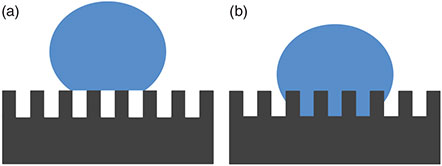
On a flat surface, the contact angle is governed by Young’s equation and is dependent on the free energies of the solid–liquid, solid–gas, and liquid–gas interfaces, resulting in a maximum attainable contact angle of ~120°.[24] However, as the surface roughness increases, so does the surface area, which in turn increases the apparent surface energy. The contact angle must increase accordingly in order to balance the greater surface energy between the substrate and the droplet in accordance with Young’s equation.[24] A high contact angle does not, however, directly relate to the Lotus Effect as low sliding angles are also required, and these are not necessarily dependent on the contact angle.[25] On a rough surface, the droplet can typically reside in one of two states: it can either contact the peaks of the structure with small pockets of air underneath, forming a liquid–air, liquid–solid, or solid–air composite interface or it can fill the grooves having direct contact with the solid substrate, forming a liquid–solid interface only, as shown schematically in Fig. 1. These two states are known as the Cassie and Wenzel states, respectively.[26–29] It is known that the Cassie state is desirable to achieve low sliding angles as there is significantly a lower degree of adhesion of the droplet to the surface due to the smaller solid–liquid contact area.[30,31]
|
The sliding angle will increase as the solid–liquid contact area increases due to greater surface adhesion. However, it has been shown that when the roughness factor exceeds a critical level, the WCA will increase further, while the sliding angle begins to decrease.[30] The reduction in sliding angle is the result of the transition of the dominant hydrophobicity mode from Wenzel’s to Cassie’s, due to an increase in the amount of air being trapped between the solid surface and droplet. The relationship between the WCA and the surface free energies in this case is less related to Young’s equation and more to the Cassie–Baxter equation, which describes the interaction between a droplet and a heterogeneous surface consisting of two materials, in this case, solid and air.
The impact of surface roughness has been extensively studied. In contrast, there have been few studies systematically investigating the effect of roughness on both the WCA and sliding angle. One such study carried out by Miwa et al. employed the sublimation of aluminium acetylacetonate and varied ratios of boehmite powder and ethanol to form a rough surface.[25] Although Miwa et al. showed control in varying the topography, and in turn the level of roughness, the surface topography was quite random with no consistent periodicity.
In this paper, we examine the effect of regular controlled surface roughness on the water contact angle and sliding angle by systematically varying the periodicity of a surface by incorporating silica nanoparticles of varying sizes of 58–1428 nm into a coating.
Results and Discussion
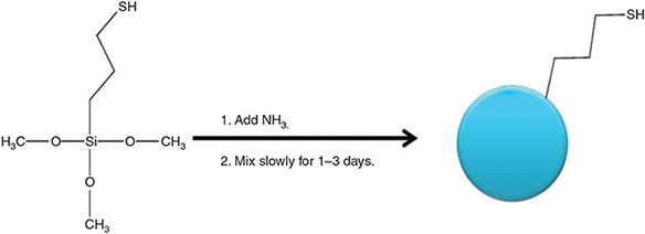
Highly monodisperse, spherical silica particles with thiol surfaces were synthesized using the modified Stöber process employing (3-mercaptopropyl)trimethoxysilane (MPTMS), as used by Mangos et al., and shown in Fig. 2.[32] By using this method, the particle size can be controlled from 50 to over 1000 nm by controlling the reactant concentrations, where the mercapto moiety maintains dispersibility during synthesis and in a range of solvents used for spin coating.
|
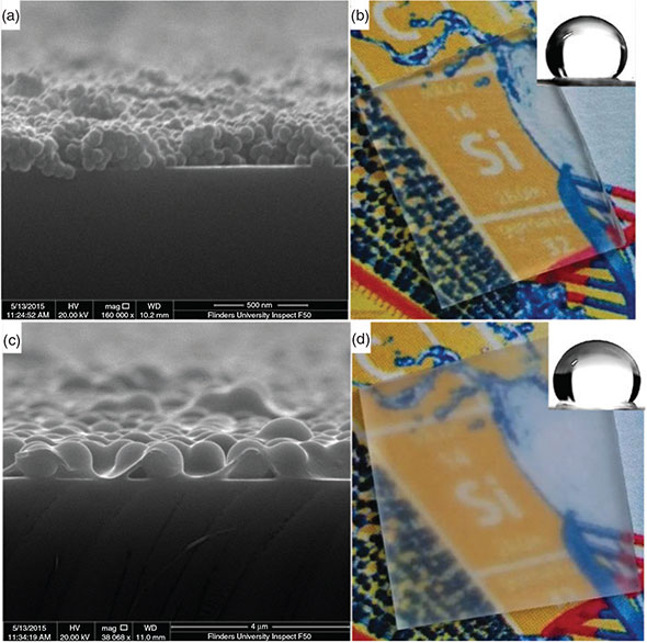
The weight ratio of 3 : 7 for PDMS/silica was chosen to achieve minimum void space, while ensuring that the surface is dominated by the silica spheres to achieve the desired roughness. The maximum theoretical packing density of equal spheres ranges from 64 % to 74 % depending on the randomness of the packing, and in this case, the lower binder concentration results in the desired surface topography as can be seen in Fig. 3, which shows a cross-section image of the surface.
|
The WCA decreased when the final film concentration of the water-repellent polymer reaches 40 wt-%, and above which is due to the surface topography becoming more planar and the top surface approaching that of pure PDMS, which has a contact angle of ~105°.
A standard concentration of silica suspension and spin rate were used for most samples. In contrast, a lower concentration and a much higher spin rate were used for the 58-nm particle film as the small particles formed a significantly thicker paste, which resulted in a thicker film with more contours, as consistent with the observations of Timofeeva et al.[33] The slower spin rate for films prepared with particles of >1 μm in size was required to ensure complete and uniform coverage of the surface.
The spin coating conditions chosen result in a ‘monolayer’ of particles on the surface with PDMS as the binder as can also be seen in Fig. 3. The impact of the surface roughness on optical properties can be seen in Fig. 3b, d, which shows that the coating employing the 1050-nm particles results in significant haze when compared with that prepared from the 58-nm particles.
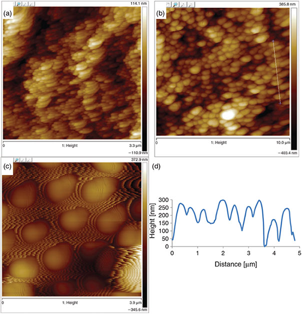
Atomic force microscopy (AFM) analysis (Fig. 4) shows that the average distance between peaks were 58, 505, and 1006 nm, for films A, B, and C, respectively, corresponding to the particle size measured from dynamic light scattering (DLS), and indicating close-to-ideal packing of the particles on the surface.
|
The average trough-to-peak height from the measured AFM data was 15, 83, and 173 nm for films A, B, and C, respectively. Lotus leaves have a peak-to-trough height of 780 nm for the nonacosanol tubules (which are 0.3–1.1 µm in length and 0.1–0.2 µm in diameter), and this is within the range of surface topography obtained in this study.[34,35] By increasing the size of the particles, we are able to control the peak-to-trough height and peak-to-peak distance, which influence the sliding angles of the films.
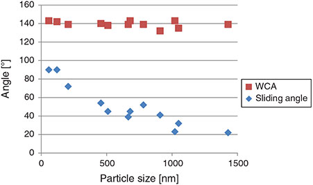
Interestingly, the WCA does not change significantly across the range of surface topography produced by the 58–1428-nm particles, as shown in Fig. 5.
|
The sliding angle decreases monotonically from complete adhesion at 90° for the 58-nm particle film to 22° for the 1428-nm particle film for 20 µL droplets, as shown in Fig. 5. The lower sliding angles for the larger particle films can be attributed to the droplets transitioning from the Wenzel to Cassie state as the particle size increases, whereby pockets of air are more likely to be trapped between the droplet and the substrate, thereby increasing the liquid-to-air interface. However, the data in Fig. 5 do not show a sharp transition to a Cassie-dominant hydrophobic mode.
The sliding angle does not decrease to less than 10°, indicating that the droplet has not completely transitioned to the Cassie state even when the larger particles are used.
Conclusions
Films with controlled surface roughness periodicity were created by forming a ‘monolayer’ of particles ranging in size from 58 to 1428 nm in a PDMS matrix. The WCA increased from 105° for a smooth PDMS surface to 140° for the roughened surfaces. However, this value remained approximately constant for all nanoparticle-roughened surfaces.
The sliding angle decreased monotonically from a pinned droplet at 90° for the 58-nm particle film to a sliding angle of 22° for films comprising 1428-nm particles. The transition from the Wenzel to Cassie state was not sharp, and instead indicated a gradual change across the entire range of topography created in this report. By improving our understanding of the relationship between surface topography and WCA and sliding angles, we can further develop easy cleaning and self-cleaning technologies, which have a broad range of applications from medical to power generation.
Experimental
Thiol-Functionalized silica nanoparticles were synthesized via a revised Stöber method shown by Mangos et al. and presented in Fig. 1.[32] MPTMS was supplied by Sigma-Aldrich and 30 % ammonia was supplied by Chem Supply. The concentration of MPTMS was varied in an ammonia solution and gently mixed for 1–3 days depending on the particle size being synthesized as presented in Table 1. These samples were vacuum-filtered with 11-µm filter paper to remove any agglomerates, and then particles with sizes greater than 200 μm were centrifuged at 2550 g for 60 min, washed with water, and dried. Particles with sizes of less than 200 μm were bubbled with air overnight to remove any ammonia, and 5 mL of hydrochloric acid was added to lower the pH and force the particles to crash out. The particles were then easily centrifuged at 2550 g for 5 min, washed, and dried in an oven at 45°C overnight. Upon collection, the samples were dispersed in acetone to make a 20 % w/v suspension which was then sonicated. Chlorobenzene was then added to make a 10 % w/v suspension to improve the dissolution of PDMS in solution. The 58-nm particle suspension was made to 5 % with acetone and then 2.5 % with chlorobenzene to improve final film consistency. A solution of 12 % by weight PDMS in chlorobenzene was added to achieve a PDMS-to-silica ratio of 3 : 7 in the final dry film. This suspension was spin-coated onto cleaned glass substrates with a ramp speed of 300 rpm for 1 s and 2500 rpm for 30 s (4000 rpm for 58-nm particle film and 2000 rpm for films with particles of ≥1 µm in size). Samples were then dried at 140°C in air.
|
Contact angles were measured on a Sinterface Profile Analysis Tensiometer 1.
Topography was analyzed using the Inspect FEI F50 scanning electron microscope and VEECO multimode atomic force microscope in tapping mode.
Acknowledgements
SEM and AFM experiments were carried out using the facilities of Flinders University, supported by the Australian Microscopy and Microanalysis Research Facility. This research was performed as part of the Australian Solar Thermal Research Initiative (ASTRI), a project supported by the Australian Government through the Australian Renewable Energy Agency (ARENA).
References
[1] S. Nishimoto, B. Bhushan, RSC Adv. 2013, 3, 671.| Crossref | GoogleScholarGoogle Scholar | 1:CAS:528:DC%2BC38XhvVertbvK&md5=d0c3b50dce5a86644a04fd48b96201d4CAS |
[2] G. Srilakshmi, V. Venkatesh, N. C. Thirumalai, N. S. Suresh, Renewable Sustainable Energy Rev. 2015, 45, 698.
| Crossref | GoogleScholarGoogle Scholar |
[3] G. A. Mastekbayeva, S. Kumar, Sol. Energy 2000, 68, 135.
| Crossref | GoogleScholarGoogle Scholar |
[4] S. A. M. Said, Appl. Energy 1990, 37, 73.
| Crossref | GoogleScholarGoogle Scholar | 1:CAS:528:DyaK3cXlsFGku7s%3D&md5=4fbf19c45f4442bc56bdc78341065c33CAS |
[5] A. Nakajima, K. Hashimoto, T. Watanabe, K. Takai, G. Yamauchi, A. Fujishima, Langmuir 2000, 16, 7044.
| Crossref | GoogleScholarGoogle Scholar | 1:CAS:528:DC%2BD3cXltVShsL0%3D&md5=066c12c4185905c310e32782c22787fcCAS |
[6] N. Wang, D. Xiong, Y. Deng, Y. Shi, K. Wang, ACS Appl. Mater. Interfaces 2015, 7, 6260.
| Crossref | GoogleScholarGoogle Scholar | 1:CAS:528:DC%2BC2MXjvFygs7Y%3D&md5=8f1064f7da3646b2cc17c301c0dab668CAS | 25749123PubMed |
[7] N. J. Shirtcliffe, G. McHale, M. I. Newton, Langmuir 2009, 25, 14121.
| Crossref | GoogleScholarGoogle Scholar | 1:CAS:528:DC%2BD1MXnsFemtb4%3D&md5=5fdbf75e3da50474f3c200d27fa54cc8CAS | 20560556PubMed |
[8] Z. Guo, W. Liu, Plant Sci. 2007, 172, 1103.
| Crossref | GoogleScholarGoogle Scholar | 1:CAS:528:DC%2BD2sXkvFGitL8%3D&md5=34889b1433203c6282499454b2945ca9CAS |
[9] K.-C. Chang, H. Chen, C.-K. Huang, S.-I. Huang, J. Appl. Polym. Sci. 2007, 104, 1646.
| Crossref | GoogleScholarGoogle Scholar | 1:CAS:528:DC%2BD2sXjs1Gqt7w%3D&md5=7444c6acb363d6fa2f569db367901699CAS |
[10] A. Nakajima, A. Fujishima, K. Hashimoto, T. Watanabe, Adv. Mater. 1999, 11, 1365.
| Crossref | GoogleScholarGoogle Scholar | 1:CAS:528:DyaK1MXnt1Kgur0%3D&md5=8b77fd4fd9bf5a3f7faf04685bbff0daCAS |
[11] T. Sun, L. Feng, X. Gao, L. Jiang, Acc. Chem. Res. 2005, 38, 644.
| Crossref | GoogleScholarGoogle Scholar | 1:CAS:528:DC%2BD2MXkt1aju7k%3D&md5=bfcdacf17a94e2dd69479db9dad4ad88CAS | 16104687PubMed |
[12] Y.-Y. Zhang, Q. Ge, L.-L. Yang, X.-J. Shi, J.-J. Li, D.-Q. Yang, E. Sacher, Appl. Surf. Sci. 2015, 339, 151.
| Crossref | GoogleScholarGoogle Scholar | 1:CAS:528:DC%2BC2MXjvVyhs78%3D&md5=be840fd8fda9626fac533dd89a4197f5CAS |
[13] Y. Lu, S. Sathasivam, J. Song, C. R. Crick, C. J. Carmalt, I. P. Parkin, Science 2015, 347, 1132.
| Crossref | GoogleScholarGoogle Scholar | 1:CAS:528:DC%2BC2MXjsF2hsrw%3D&md5=0cbda0d0012aed9177c4d009fbb58160CAS | 25745169PubMed |
[14] C.-H. Xue, X.-J. Guo, J.-Z. Ma, S.-T. Jia, ACS Appl. Mater. Interfaces 2015, 7, 8251.
| Crossref | GoogleScholarGoogle Scholar | 1:CAS:528:DC%2BC2MXlslKjtb0%3D&md5=5d5b0bf173211822feabcf55e4ba7368CAS | 25832484PubMed |
[15] Y. Wang, M. Li, T. Lv, Q. Wang, Q. Chen, J. Ding, J. Mater. Chem. A 2015, 3, 4967.
| Crossref | GoogleScholarGoogle Scholar | 1:CAS:528:DC%2BC2MXhtVWhtbo%3D&md5=6b2b77e722f525a92dc0bb78e8beb50dCAS |
[16] J. Bravo, L. Zhai, Z. Wu, R. E. Cohen, M. F. Rubner, Langmuir 2007, 23, 7293.
| Crossref | GoogleScholarGoogle Scholar | 1:CAS:528:DC%2BD2sXls1KqsLY%3D&md5=1943970037af847da0d2608ae6867b43CAS | 17523683PubMed |
[17] Y. Coffinier, S. Janel, A. Addad, R. Blossey, L. Gengembre, E. Payen, R. Boukherroub, Langmuir 2007, 23, 1608.
| Crossref | GoogleScholarGoogle Scholar | 1:CAS:528:DC%2BD2sXjtVaruw%3D%3D&md5=ff358392282b8d449551265261dc19a9CAS | 17279635PubMed |
[18] B. Qian, Z. Shen, Langmuir 2005, 21, 9007.
| Crossref | GoogleScholarGoogle Scholar | 1:CAS:528:DC%2BD2MXpsVGhu74%3D&md5=3bc1d861cd66a452a801541f1f5ce9f4CAS | 16171323PubMed |
[19] J. Zhang, S. Seeger, Adv. Funct. Mater. 2011, 21, 4699.
| Crossref | GoogleScholarGoogle Scholar | 1:CAS:528:DC%2BC3MXhtlWlu7%2FN&md5=26d5190a1bb70e2520ffa4498ef663a4CAS |
[20] S.-J. Choi, T.-H. Kwon, H. Im, D.-I. Moon, D. J. Baek, M.-L. Seol, J. P. Duarte, Y.-K. Choi, ACS Appl. Mater. Interfaces 2011, 3, 4552.
| Crossref | GoogleScholarGoogle Scholar | 1:CAS:528:DC%2BC3MXhsVCrsLfI&md5=cb098f8dd5e7e5f0125108aaef103ea2CAS | 22077378PubMed |
[21] R. Li, C. Chen, J. Li, L. Xu, G. Xiao, D. Yan, J. Mater. Chem. A 2014, 2, 3057.
| Crossref | GoogleScholarGoogle Scholar | 1:CAS:528:DC%2BC2cXhvFCqurg%3D&md5=4ca25a964e463575c035d62ab9a0c559CAS |
[22] J. Wu, N. Wang, L. Wang, H. Dong, Y. Zhao, L. Jiang, ACS Appl. Mater. Interfaces 2012, 4, 3207.
| Crossref | GoogleScholarGoogle Scholar | 1:CAS:528:DC%2BC38XntlOiurg%3D&md5=496765e5933a14c03ab78ba451e58d79CAS | 22620260PubMed |
[23] A. D. Tserepi, M.-E. Vlachopoulou, E. Gogolides, Nanotechnology 2006, 17, 3977.
| Crossref | GoogleScholarGoogle Scholar | 1:CAS:528:DC%2BD28XhtVSrsbjN&md5=9aebb13c91da18fe04a75e4aad2fbf7cCAS |
[24] H. M. Shang, Y. Wang, S. J. Limmer, T. P. Chou, K. Takahashi, G. Z. Cao, Thin Solid Films 2005, 472, 37.
| Crossref | GoogleScholarGoogle Scholar | 1:CAS:528:DC%2BD2cXhtVartrnJ&md5=50b8e93a17dd9acfe2a40ad2adbb22c2CAS |
[25] M. Miwa, A. Nakajima, A. Fujishima, K. Hashimoto, T. Watanabe, Langmuir 2000, 16, 5754.
| Crossref | GoogleScholarGoogle Scholar | 1:CAS:528:DC%2BD3cXjsF2qtro%3D&md5=ea27a999b8fd31e77b29303a79863d41CAS |
[26] N. A. Patankar, Langmuir 2003, 19, 1249.
| Crossref | GoogleScholarGoogle Scholar | 1:CAS:528:DC%2BD3sXjvFektQ%3D%3D&md5=3668c8ed10af74580e5cc0f72972a829CAS |
[27] B. He, J. Lee, N. A. Patankar, Colloids Surf., A 2004, 248, 101.
| Crossref | GoogleScholarGoogle Scholar | 1:CAS:528:DC%2BD2cXpsVSit7Y%3D&md5=6a6d2a96ab5655416307227878761ceaCAS |
[28] R. N. Wenzel, J. Phys. Colloid Chem. 1949, 53, 1466.
| Crossref | GoogleScholarGoogle Scholar | 1:CAS:528:DyaG3cXhs12nsA%3D%3D&md5=ff29a9035ecd8b53243640f3868906d9CAS |
[29] A. B. D. Cassie, S. Baxter, Trans. Faraday Soc. 1944, 40, 546.
| Crossref | GoogleScholarGoogle Scholar | 1:CAS:528:DyaH2MXhsFKqsA%3D%3D&md5=c28a9bb140c2b8e22caadaba8699d3caCAS |
[30] Z. Yoshimitsu, A. Nakajima, T. Watanabe, K. Hashimoto, Langmuir 2002, 18, 5818.
| Crossref | GoogleScholarGoogle Scholar | 1:CAS:528:DC%2BD38Xks12rtLc%3D&md5=d81d35d3331c2a51e0771b253cf09d8eCAS |
[31] A. Lafuma, D. Quere, Nat. Mater. 2003, 2, 457.
| Crossref | GoogleScholarGoogle Scholar | 1:CAS:528:DC%2BD3sXls1elsL0%3D&md5=b57650f48ff3aa4aff7a34fcf435ee84CAS | 12819775PubMed |
[32] D. N. Mangos, T. Nakanishi, D. A. Lewis, Sci. Technol. Adv. Mater. 2014, 15, 015002.
| Crossref | GoogleScholarGoogle Scholar |
[33] E. V. Timofeeva, D. S. Smith, W. Yu, D. M. France, D. Singh, J. L. Routbort, Nanotechnology 2010, 21, 215703.
| Crossref | GoogleScholarGoogle Scholar | 20431197PubMed |
[34] N. Michael, B. Bhushan, Microelectron. Eng. 2007, 84, 382.
| Crossref | GoogleScholarGoogle Scholar | 1:CAS:528:DC%2BD2sXhvVCltrc%3D&md5=0f1e8c4b5e2cc1cb05555a36016cdafbCAS |
[35] K. Koch, B. Bhushan, Y. C. Jung, W. Barthlott, Soft Matter 2009, 5, 1386.
| Crossref | GoogleScholarGoogle Scholar | 1:CAS:528:DC%2BD1MXjsFaisbs%3D&md5=44ff9bf2717eb2ea97f24e80606f14b2CAS |
* The corresponding author, David Lewis, is the winner of the 2014 RACI Applied Research Award.