

Preparation and Characterization of Catalysts for Clean Energy: A Challenge for X-rays and Electrons
Rosalie K. Hocking A B D , Shery L. Y. Chang A C , Douglas R. MacFarlane A B and Leone Spiccia A BA School of Chemistry, Monash University, Clayton, Vic. 3800, Australia.
B Australian Centre for Electromaterials Science, ACES.
C Monash Centre for Electron Microscopy, Monash University, Clayton, Vic. 3800, Australia.
D Corresponding author. Email: rosalie.hocking@monash.edu

Rosalie Hocking is currently a research fellow working for the Australian Centre for Electromaterials Science. Her research focuses on understanding the mechanistic chemistry of metal oxides and sulfides as chemical catalysis for hydrogen generation. |

Shery (Lan Yun) Chang is currently a research fellow jointly appointed by the Monash Centre Electron Microscopy and the School of Chemistry at Monash University. Her research focuses on the development and application of advanced transmission electron microscopy techniques to the structure–property relationships of nanocatalysts at an atomic level. |

Douglas MacFarlane is an ARC Federation Fellow at Monash University. He is also the program leader of the Energy Program in the ARC funded Australian Centre for Electromaterials Science. His research interests include the development of ionic liquids for use in catalysis and energy storage. |

Leone Spiccia is currently Professor of Chemistry at Monash University. His research interests include the development of photoactive and redox active metal complexes for incorporation into dye sensitized solar cells and bio-inspired catalysts for use in water splitting devices made from earth abundant elements. |
Australian Journal of Chemistry 65(6) 608-614 https://doi.org/10.1071/CH12016
Submitted: 16 January 2012 Accepted: 6 March 2012 Published: 18 May 2012
Abstract
One of the most promising approaches to addressing the challenges of securing cheap and renewable energy sources is to design catalysts from earth abundant materials capable of promoting key chemical reactions including splitting water into hydrogen and oxygen (2H2O → 2H2 + O2) as well as both the oxidation (H2 → 2H+) and reduction (2H+ → H2) of hydrogen. Key to elucidating the origin of catalytic activity and improving catalyst design is determining molecular-level structure, in both the ‘resting state’ and in the functioning ‘active state’ of the catalysts. Herein, we explore some of the analytical challenges important for designing and studying new catalytic materials for making and using hydrogen. We discuss a case study that used the combined approach of X-ray absorption spectroscopy and transmission electron microscopy to understand the fate of the molecular cluster, [Mn4O4L6]+, in Nafion.
Introduction
Securing cheap and renewable sources of energy is one of the greatest challenges of the 21st century.[1,2] Compared with other possibilities for renewable energy sources, it is argued that solar energy has the greatest potential to provide sufficient energy to meet the world’s needs.[3,4] The challenge of using solar energy is the cost, which is still far from comparable to fossil fuels.[5] A promising approach to utilizing solar energy is photo-electrochemical splitting of water (H2O) into hydrogen (H2) and oxygen (O2) and to then use the hydrogen for energy. To split water, catalysts must be developed to implement two key chemical reactions; one to oxidize water into protons and dioxygen (2H2O → 4H+ + O2 + 4e–) and the other to reduce protons to hydrogen (2H+ + 2e– → H2). In addition, in order to use the hydrogen in fuel cells, the oxidation of hydrogen (H2 → 2H+ + 2e–) needs to be coupled to oxygen reduction.[5,6] If this could be done cheaply and efficiently without catalyst deactivation, solar powered water splitting could be used to make hydrogen, which could be used 24 h a day in fuel cells and stored until needed.[5]
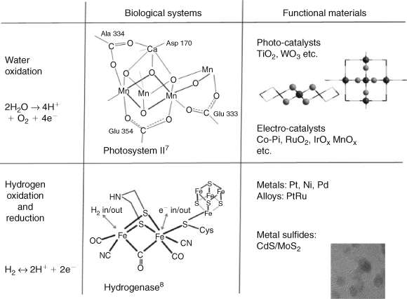
There are two key approaches to the design of catalytic materials. One is to develop and apply our knowledge of how enzymes catalyze processes in biology, the other is to use and develop our knowledge of functional materials. In the bio-inspired approach, we draw our inspiration from nature, and ultimately try to understand the way nature has designed catalysts. This involves probing the structures and properties of two key catalytic centres (i) Photosystem II[9–11] (Fig. 1 upper), which catalyzes water oxidation; and hydrogenase (Fig. 1 lower), which catalyzes both the oxidation and reduction of hydrogen. The materials approach to this problem is to learn about the properties of existing materials and to use this knowledge in the creation of new and improved materials. Among the most effective materials for catalytic water splitting are the metal oxides including photocatalysts TiO2,[12] WO3,[13] MnO2[14,15] and electrocatalysts RuO2,[16] IrO2[17,18]and Co-Pi.[19,20] For the reduction of protons Pt[21–23] and alloys[24,25] are the best known, while several other materials have been reported as active catalysts including Ni[26] and Pd,[26] photocatalysts, MoS2/CdS,[27] PEDOT polymer,[28] and several molecular compounds.[29,30] Of the three reactions described above, the hardest to mimic has been hydrogen oxidation, with the only known catalysts being hydrogenase (vide supra) and Pt and Pt alloys.[24,25]
Despite the increasing number of materials that are known to catalyze the reactions described above, none have proved sufficiently cheap and robust for long-term applications. For example, one of the most efficient water splitting systems reported to date is a composite system of Cu2O, Al doped ZnO, TiO2 and Pt; however, it becomes less active after an hour of operation.[31] If we could maintain the photo-efficiency of this catalyst and stop its deactivation process, the goal of generating cheap hydrogen would be within reach. To improve this, and other catalysts, a full understanding of both the mechanisms of action and deactivation need to be elucidated. Key to these, is understanding the atomic- and molecular-level structure of the material, before during, and after catalysis.[5,32]
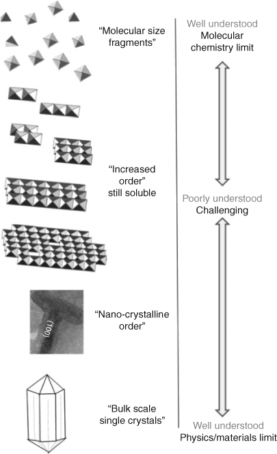
To understand how X-rays and electron based methods of analysis can assist us in these endeavours it is helpful to think about how matter is probed at the atomic- and molecular-level more generally. Any material we wish to study can be depicted at some point on the scale shown in Fig. 2. At the bottom of the scale are materials that form single crystals, whereas at the top are molecular species. The structures of many materials including many catalysts fall between the two limits.
|
Materials on the right hand side of the scale exist as bulk single crystals[33] and can usually be studied with X-ray diffraction. Once the geometric structure is well estimated the electronic structure of the materials can be calculated with for example, plane wave density functional theory (DFT).[34] So at the single crystal limit, both the electronic structure and geometric structure of materials can be well understood. At the other end of the spectrum are molecular materials, which are well suited to study by the inorganic spectroscopic techniques including electron paramagnetic resonance,[35] Mössbaur,[36] UV-Vis-NIR,[37] and magnetic circular dichroism.[38] These techniques focus on a metal centre via its electronic transitions or magnetic signature, or a combination of both. This has contributed substantially to understanding metal sites in biology[39,40] and molecular inorganic compounds. These results are often correlated with those from computational methods to gain a good understanding of the relationship between structure and function.[39,41,42] So materials at the top and the bottom of the size scale are well understood in terms of both electronic structure and geometric structure.
While techniques are available to study materials at the ‘molecular limit’ and single crystal ‘materials limit’, materials falling in between are affected by material size, disorder in crystallinity, defects etc. and their study can be extremely challenging. One way to overcome this is to combine complementary techniques that can probe different properties of the material. Two techniques that work well together for this purpose are X-ray absorption spectroscopy (XAS) and transmission electron microscopy (TEM).
X-ray Absorption Spectroscopy
An XAS experiment fundamentally measures absorption as a function of photon energy.[43,44] XAS has several advantages over other types of spectroscopic techniques particularly for studying materials in complex matrices, such as electro-catalysts. First, an X-ray absorption edge is element specific. Second, XAS does not need the material to be in any particular form. So, for example, an amorphous material can be studied as well as the surface of a functional active catalyst, or an electro-catalyst in situ.[45–48]
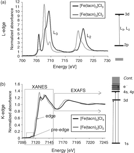
Two families of XAS spectra are shown in Fig. 3. The upper spectrum is typical of a transition metal L2,3-edge, the lower spectrum is typical of a K-edge. The spectra are of two common coordination compounds, [Fe(tacn)2]Cl2 and [Fe(tacn)2]Cl3. The spectra are different because of the differences in selection rules that dominate the spectra. A transition metal L-edge is dominated by the dipole allowed 2p → 3d transition, the shape of these spectra are dominated by ligand field and covalency type effects.[38] The K-edge spectrum as shown, has three regions: (i) the pre-edge (1s → 3d transition); (ii) the edge (1s → 4s,4p transition), together these two regions are often referred to as the X-ray absorption near edge structure or XANES; (iii) the extended X-ray absorption fine structure (EXAFS) region. This provides structural information, via the interferences of the ejected photo-electron,[49,50] discussed further below. Note that for heavier elements EXAFS can be determined from the L3 edge as the spin orbit splitting between the L3 and L2 edges increases, and that the L-edges can be referred to more generically as XANES.
|
Transmission Electron Microscopy
As recently as the last few decades, if a material did not form single crystals it was not possible to definitively assign the regular atom spacing within the material. This meant that little was known about the structure of many common materials. This changed with the advent of TEM. The mechanisms of diffraction and high-resolution imaging in TEM have many aspects in common with those of X-ray diffraction and EXAFS. All involve obtaining structural information by the interference of scattered waves; TEM utilizes electrons with energies in the range 100–300 keV, EXAFS utilizes photoelectrons with energies from several hundred up to several thousand eV. For the case of electron diffraction in a TEM experiment, like X-ray and neutron diffraction, the constructive interference of scattered electrons gives rise to diffraction peaks. However, unlike X-rays and neutrons, the strength of the electrostatic interaction between the incident electrons and the electrons and nuclei within the specimen means that diffraction patterns can be formed from very small volumes of material. This aspect gives electron diffraction an advantage in the characterization of nanomaterials and materials with only microcrystalline order. For catalysis, this means that the structure of the materials can still be proved even when the materials are highly disordered or the size of the materials is only a few nanometres (or 10 s of Angstroms). For example, the surface defect structures of platinum nanocatalysts have been determined using a high-resolution TEM (HRTEM) technique.[22,51] In addition, when only electrons scattered to high angles are collected to form images under scanning focussed electron probe geometry (HAADF-STEM mode), chemical composition of the materials can be obtained at atomic resolution.[25,52]
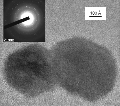
Fig. 4 shows a bright field TEM image of manganese oxide nanoparticles embedded in a Nafion film and the inset shows the corresponding selected-area electron diffraction pattern. In selected-area diffraction (SAD), an aperture is placed in an intermediate image plane so that the diffraction pattern is obtained only from the specimen area of interest, which is typically several tens to several hundreds of nm wide.[53] The SAD pattern reveals the atomic plane spacings, thus it can be used to determine the phase of the material (speciation). SAD is particularly useful when the size of crystals are too small for X-ray or neutron diffraction, as is often the case for catalytic materials.
|
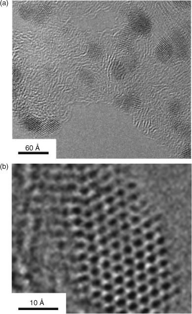
In imaging mode, TEM can provide direct information on the size and structure of materials. High-resolution phase-contrast (HRTEM) imaging is a widely used technique to characterize nanoparticles. The characteristic lattice fringe contrast arises from the interference of the electron waves in the image plane, providing structural information at atomic resolution. The technique is particularly useful when the particle size is too small to obtain an adequate diffraction signal. Fig. 5 shows an example of a HRTEM image of PtRu nanoparticles supported on carbon black. These particles are only 2 nm in size. Even SAD cannot reveal any structural information (diffraction peaks) for supported particles of such small size. However, the HRTEM image clearly shows that these particles are crystalline. Analysis of the lattice fringe spacing reveals that these particles have a structure very similar to that of pure platinum. Recently, with the advent of TEM with aberration correctors, the resolution of HRTEM images is routinely better than 1 Å. Another advantage of aberration correction is that the image ‘delocalization’ is greatly reduced, therefore allowing imaging of atomic structure of materials with greater accuracy.[22] For example, the individual atomic column of PtRu nanoparticles can be clearly seen in the aberration-corrected TEM image shown in Fig. 5b.
|
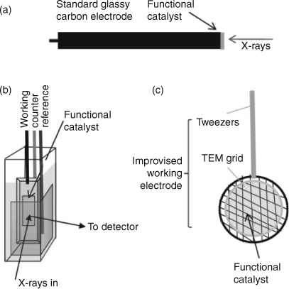
In employing any analytical approach to studying catalysis, it is important to capture the material in as close as possible to its functional state. This is a challenge for analytical chemistry as many catalytic materials have quite complex components that make analytical experiments difficult. For example, it is common for catalysts to be supported or to be made of composite materials, while others need an over-potential to work, which can change material composition. It is therefore important to develop new methodologies that enable us to study catalytic materials as close as possible to their functional state. Fig. 6 shows the adaption of both a transmission electron microscopy experiment and an X-ray absorption experiment to study an electro-catalyst. An electrode can be studied ex situ (the electrode at various states of catalytic cycling) and in situ with an over-potential applied. Using electron microscopy techniques, a standard TEM grid can be modified to be a working electrode by growing or depositing a catalytic film on the grid and subjecting it to the active conditions of catalysis.
|
Both XAS and TEM have limitations in studying materials. While XAS is element specific, its sensitivity decreases in going out from, with increasing atomic distance; or when atoms are far away (>7 Å) from the centre of the absorbing atom. This means, for example, that it is difficult to get information about particle size. TEM can also be limited, as it only gives the ‘projected’ structure of the material. In other words, TEM only gives two-dimensional structural information. This means, for example, that it is difficult to pinpoint the exact location of a dopant atom within the matrix compared with XAS.[54] By combining the approaches, the limitations of each technique can be overcome providing detailed molecular level understanding of functional catalyst materials, an example of which is described below.
A Case Study: Combining XAS and TEM to Understand the Fate of a Molecular Compound in Nafion
The molecular nature of the active site of photosystem II (PSII) has meant there has been a significant synthetic effort directed towards making molecular mimics, both to better understand PSII and to design better catalysts. An efficient manganese water-oxidation catalyst was prepared by doping a tetranuclear manganese cluster [Mn4O4L6]+ (L = diaryl phosphinate) into at Nafion polymer matrix that had been deposited onto conductive electrodes (e.g. glassy carbon, fluoride doped tin oxide). The embedded catalyst was shown to sustain water oxidation catalysis for an extended period on illumination with visible light and application of a potential bias (1.0 V v. Ag/AgCl). The photocurrent generated by this photoanode was confirmed to originate from water oxidation through isotopic labelling experiments (formation of 36O2 was found on introduction of 18OH2 into the solvent). Removal of water by working in anhydrous organic solvent led to a complete loss of photocurrent.[55] However, there were still questions about the fate of the complex in Nafion and about the actual catalytic cycle leading to the observed catalysis.[55–58] This prompted us to examine the problem further using XAS.
Initial studies focussed on the changes that took place when the cluster was loaded into Nafion by XAS. The results from the initial set of experiments are shown in Fig. 7.
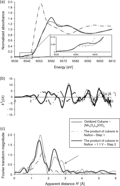
|
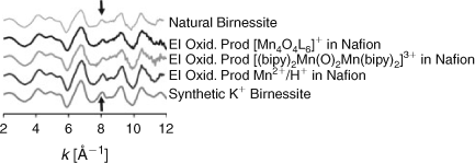
From the XANES data shown in Fig. 7a it can be seen a comparison of the XANES of [Mn4O4L6]+ and the XANES of [Mn4O4L6]+ loading into Nafion that there is a significant shift in the XANES intensity to lower energy (– to –.–), which is consistent with the reduction of the MnIIIMnIV centres to MnII species. Application of a potential bias results in oxidation of the doped material to a valency state similar to that of the initial [Mn4O4L6]+ that was doped into Nafion. However, a careful analysis of the EXAFS reveals that the material formed upon electro-oxidation is more ordered (Fig. 7c), as evidenced by the second peak of the Fourier transform indicated by the arrow, which changes from being split from the non-symmetric cubane to having only two peaks. A second series of experiments was conducted with different starting materials (Mn2+/H+) and [(bipy)2Mn(O)2Mn(bipy)2]3+, which were also shown to be active water oxidation catalysts after loading into Nafion. It was found that upon re-oxidation, they all gave almost identical XAS spectra (Fig. 8). Moreover, the same spectra could be reproducibly generated on cycling, with application of a bias and followed by irradiation with light, and so on, which suggested that a clean transformation between oxidized and reduced compounds was taking place during catalysis. It was, therefore, concluded that the likely candidates for the water oxidation catalyst were not the materials initially doped in Nafion (as originally thought) but a common product, which could form from the three different starting materials. Given that the active material could be generated by electro-oxidation of Mn2+, doped in Nafion, the likely candidates were manganese oxides or small soluble clusters. From the EXAFS of the material, it could be shown that the short range connectivity of the material resembled that of the manganese oxide phase birnessite.[59] However, it was not known whether the EXAFS was from molecular-sized manganese clusters or an oxide material. To further examine whether manganese oxide particles had formed in the Nafion film, high-resolution TEM studies were undertaken on both the oxidized and reduced states of the Nafion films doped with either [Mn4O4L6]+ and Mn2+ from an acidified solution. Nanoparticles (1–2 nm diameter) were identified in the TEM image of the oxidized films from both, whereas no nanoparticles were identified in the reduced state.[59]
|
In addition to discovering the origin of the catalytic material, XAS experiments were used to show that the origin of the photo-catalysis was from photo-reduction of the birnessite-like phase to Mn2+, providing a biogeochemical-like cycle for the observed water oxidation mechanism.[59] In nature, such light sensitive manganese oxide materials are produced by bacteria, and then dissolve on irradiation forming Mn2+ and oxygen.[60–62]
Conclusions
Many catalyst materials are difficult to study by traditional spectroscopic approaches, being neither molecular materials nor fully ordered crystalline phases. By combining TEM and XAS, materials that sit between these two limits can be investigated providing insights into the origin of catalysis in these analytically challenging systems. The power of combining multiple experimental methods to elucidate reaction mechanisms has been nicely demonstrated in our investigations of the origin of water oxidation catalysis by photoanodes comprising Mn complexes embedded in Nafion.
Acknowledgements
We would like to acknowledge the Australian Synchrotron for its ongoing support for our research in this area via proposals FI 3325, M2980 and FI 2370 as well as the Monash University Centre for Electron Microscopy for providing electron microscopy facilities. DRM and LS gratefully acknowledge funding from the Australian Research Council (ARC) and ARC Centre of Excellence for Electromaterials Science.
References
[1] Stemp-Morlock, The biggest challenges of the 21st century. Cosmos Magazine Online 2008, 1855.[2] A. Jha, Leading thinkers identify greatest challenges facing humanity. The Guardian 2008. www.guardian.co.uk/science/2008/feb/15/technological.challenges (verified March 2012).
[3] J. Twidell, A. Weir, Renewable Energy Resources 2006 (Taylor and Francis: New York).
[4] J.-P. Rodrigue, C. Comtois, Transportation and energy, in The Geography of Transport Systems 2010. http://people.hofstra.edu/geotrans/eng/ch8en/conc8en/ch8c2en.html (verified March 2012).
[5] T. R. Cook, D. K. Dogoutan, S. Y. Reece, Y. Surendranath, T. S. Teets, D. G. Nocera, Chem. Rev. 2010, 110, 6474.
| Crossref | GoogleScholarGoogle Scholar | 1:CAS:528:DC%2BC3cXhtl2lsb3I&md5=438de29bdee38432d249bcc4efea7a26CAS |
[6] F. A. Armstrong, Phil. Trans. R. Soc. B. 2008, 363, 1263.
| Crossref | GoogleScholarGoogle Scholar | 1:CAS:528:DC%2BD1cXktFeis78%3D&md5=19c00af68697f2b6c04e35bce313f414CAS |
[7] Y. Umena, K. Kawakami, J.-R. Shen, N. Kamiya, Nature 2011, 473, 55.
| Crossref | GoogleScholarGoogle Scholar | 1:CAS:528:DC%2BC3MXkslCmtLg%3D&md5=f7b48594fae4a870a2b3d1c7ed10df43CAS |
[8] A. S. Pandey, T. V. Harris, L. J. Giles, J. W. Peters, R. K. Szilagyi, J. Am. Chem. Soc. 2008, 130, 4533.
| Crossref | GoogleScholarGoogle Scholar | 1:CAS:528:DC%2BD1cXivV2gsbg%3D&md5=78776dcdb1d310db2a81c3b2bb905e1cCAS |
[9] J. Yano, J. Kern, K. Sauer, M. J. Latimer, Y. Pushkar, J. Bisiadka, B. Loll, W. Saenger, J. Messinger, A. Souni, V. K. Yachandra, B. Lo, Science 2006, 314, 821.
| Crossref | GoogleScholarGoogle Scholar | 1:CAS:528:DC%2BD28XhtFKit73N&md5=347b86e74bdd04fa290532ebbe2c7265CAS |
[10] B. Kok, B. Forbush, M. McGloin, Photochem. Photobiol. 1970, 11, 457.
| Crossref | GoogleScholarGoogle Scholar | 1:CAS:528:DyaE3cXltFOgtL0%3D&md5=7bcc634b1f81b1d998a3396bf222ab34CAS |
[11] G. C. Dismukes, R. Brimblecombe, G. A. N. Felton, R. S. Pyradum, J. E. Sheats, L. Spiccia, G. F. Swiegers, Acc. Chem. Res. 2009, 42, 1935.
| Crossref | GoogleScholarGoogle Scholar | 1:CAS:528:DC%2BD1MXhsVSgtb%2FL&md5=7ee1e63bbf20e924e0a4d165bd1f212dCAS |
[12] K. Fujisawa, K. Honda, Nature 1972, 238, 37.
| Crossref | GoogleScholarGoogle Scholar |
[13] G. Hodes, D. Cahen, J. Manassen, Nature 1976, 260, 312.
| Crossref | GoogleScholarGoogle Scholar | 1:CAS:528:DyaE28Xks1GlsLo%3D&md5=7b522a966ca57af743b1da1c93ff968dCAS |
[14] N. P. Luneva, V. Y. Shafirovich, A. E. Silov, J. Mol. Catal. 1989, 52, 49.
| Crossref | GoogleScholarGoogle Scholar | 1:CAS:528:DyaL1MXlslWjt7s%3D&md5=123f821dc12d14affb1434f1c89eb894CAS |
[15] V. Y. Shafirovich, N. K. Khannanov, A. E. Shilov, J. Inorg. Biochem. 1981, 15, 113.
| Crossref | GoogleScholarGoogle Scholar | 1:CAS:528:DyaL3MXmtVSkt7o%3D&md5=b57a21aef0ec376f0ee2f63993cee4b2CAS |
[16] S. Trasatti, G. Buzzanca, J. Electroanal. Chem. 1971, 29, 1.
| 1:CAS:528:DyaE3MXhtF2gtbk%3D&md5=c913e83e20598ddf17c9fdb7791e87bfCAS |
[17] M. Hara, T. W. Mallouk, Chem. Commun. 2000, 19, 1903.
| Crossref | GoogleScholarGoogle Scholar |
[18] M. Hara, C. C. Waraksa, J. T. Lean, B. A. Lewis, T. Mallouk, J. Phys. Chem. A 2000, 104, 5275.
| Crossref | GoogleScholarGoogle Scholar | 1:CAS:528:DC%2BD3cXivFeqtrY%3D&md5=eda2636fbdcffe31a7c1d54c92174094CAS |
[19] M. W. Kanan, D. G. Nocera, Science 2008, 321, 1072.
| Crossref | GoogleScholarGoogle Scholar | 1:CAS:528:DC%2BD1cXhtVSitrbP&md5=4d554995a8442318e37fd3fd4f64344fCAS |
[20] M. W. Kanan, J. Yano, Y. Surendranath, M. Dinca, V. K. Yachandra, J. Am. Chem. Soc. 2010, 132, 13692.
| Crossref | GoogleScholarGoogle Scholar | 1:CAS:528:DC%2BC3cXhtFGru7zM&md5=540cc424d400d53fa31ddfbaffecfcd3CAS |
[21] C. S. C. Bose, K. Rajeshwar, J. Electroanal. Chem. 1992, 235, 235.
[22] L. Y. Chang, A. S. Barnard, L. C. Gontard, R. E. Dunin-Borkowski, Nano Lett. 2010, 10, 3073.
| Crossref | GoogleScholarGoogle Scholar | 1:CAS:528:DC%2BC3cXptlymu7w%3D&md5=e6033f5302278eb4086edda73aef8969CAS |
[23] R. Adams, Org. Synth. 1928, 8, 463.
[24] M. S. Kim, S. Lim, N. K. Chaudhari, B. Fang, T.-S. Bau, J.-S. Yu, Catal. Today 2010, 158, 354.
| Crossref | GoogleScholarGoogle Scholar | 1:CAS:528:DC%2BC3cXhsV2ktrfO&md5=e76f48856a4f383efcbc648ab7cb220eCAS |
[25] L.-Y. Chang, S. Lazar, E. A. Baranova, C. Bock, G. A. Botton, Microsc. Microanal. 2009, 15, 1416.
| Crossref | GoogleScholarGoogle Scholar |
[26] A. J. Bard, M. A. Fox, Acc. Chem. Res. 1995, 28, 141.
| Crossref | GoogleScholarGoogle Scholar | 1:CAS:528:DyaK2MXjvFOksrc%3D&md5=6043a9013ec104828d604e3be78af8f9CAS |
[27] J. S. Jang, D. L. Ham, N. Lakshminarasimhan, W. Y. Choi, J. S. Lee, Appl. Catal. A 2008, 346, 149.
| Crossref | GoogleScholarGoogle Scholar | 1:CAS:528:DC%2BD1cXosl2ksrk%3D&md5=2257c900e8700bfa26650e85e8dcc6ceCAS |
[28] B. Winther-Jensen, K. Fraser, C. Ong, M. Forsyth, D. R. MacFarlane, Adv. Mater. (Deerfield Beach Fla.) 2010, 22, 1727.
| Crossref | GoogleScholarGoogle Scholar | 1:CAS:528:DC%2BC3cXltVyqtL8%3D&md5=fed2082535042c822df0cad820d70908CAS |
[29] T. B. Rauchfuss, Inorg. Chem. 2004, 43, 14.
| Crossref | GoogleScholarGoogle Scholar | 1:CAS:528:DC%2BD3sXps1Gmtrs%3D&md5=16b91472c4620354a4d2980edf9586afCAS |
[30] C. Tard, C. J. Pickett, Chem. Rev. 2009, 109, 2245.
| Crossref | GoogleScholarGoogle Scholar | 1:CAS:528:DC%2BD1MXlslOqsLw%3D&md5=63444de617192ccbc5115d4b4d03af6bCAS |
[31] A. Paracchino, V. Laporte, K. Sivula, M. Gratzel, E. Thimsen, Nat. Mater. 2011, 10, 456.
| Crossref | GoogleScholarGoogle Scholar | 1:CAS:528:DC%2BC3MXlvVahurg%3D&md5=4d58cdee5d0bea10131040c0b389aafdCAS |
[32] R. E. Blankenship, D. M. Tiede, J. Barber, G. W. Brudvig, G. Fleming, M. Ghirardi, M. R. Gunner, W. Junge, D. M. Kramer, A. Melis, T. A. Moore, C. C. Moser, D. G. Nocera, A. J. Nozik, D. R. Ort, W. W. Parson, R. C. Prince, R. T. Sayre, Science 2011, 332, 805.
| Crossref | GoogleScholarGoogle Scholar | 1:CAS:528:DC%2BC3MXlslylsLk%3D&md5=7fef5a2be0a1e90cdea051d4e8001fa9CAS |
[33] Note that we refer to ‘bulk scale single crystals’ to distinguish the materials from nanoscale crystals whose structure can be solved by electron diffraction.
[34] Note that this is not true for biological materials because of the very large number of atoms in the unit cell.
[35] F. A. Walker, Coord. Chem. Rev. 1999, 185–186, 471.
| Crossref | GoogleScholarGoogle Scholar |
[36] E. Murad, J. Cashion, Mossbauer Spectroscopy of Environmental Materials and their Industrial Utilization, 2003 (Kluwer Academic Publishers: Dordrecht).
[37] C. J. Ballhausen, Molecular Electronic Structures of Transition Metal Complexes, 1979 (McGraw-Hill).
[38] R. K. Hocking, E. I. Solomon, in Structure and Bonding Molecular Electronic Structures of Transition Metal Complexes, 2012, pp. 1–30 (Eds D. M. P. Mingos, P. Day, J. P. Dahl) (Springer).
[39] R. H. Holm, P. Kennepohl, Chem. Rev. 1996, 96, 2239.
| Crossref | GoogleScholarGoogle Scholar | 1:CAS:528:DyaK28Xmt1Gnu7o%3D&md5=629c145d075c206d3e92b68d25072333CAS |
[40] E. I. Solomon, M. D. Lowery, Science 1993, 259, 1575.
| Crossref | GoogleScholarGoogle Scholar | 1:CAS:528:DyaK3sXit1yksro%3D&md5=27415e236c767b287e4b50056b2fcb0fCAS |
[41] E. I. Solomon, C. Brunhold Thomas, I. Davis Mindy, J. N. Kemsley, S.-K. Lee, N. Lehnert, F. Neese, A. Skulan, Y.-S. Yang, J. Zhou, Chem. Rev. 2000, 100, 235.
| Crossref | GoogleScholarGoogle Scholar | 1:CAS:528:DyaK1MXnvF2qsLk%3D&md5=6e351a2ff92e0ae405c47f9656c448f1CAS |
[42] E. I. Solomon, M. A. Hanson, in Inorganic Electronic Structure and Spectroscopy, 1999 (Eds E. I. Solomon, A. B. P. Lever) (Wiley: New York).
[43] S. P. Cramer, K. O. Hodgson, Prog. Inorg. Chem. 1979, 25, 1.
| Crossref | GoogleScholarGoogle Scholar | 1:CAS:528:DyaL3cXksVSls7c%3D&md5=b5b74c3fe2346ead5e98bc2fe4b5a4dbCAS |
[44] H. H. Zhang, B. Hedman, K. O. Hodgson, in Inorganic Electronic Structure and Spectroscopy, 1999, pp. 513–554 (Eds E. I. Solomon, A. B. Lever) (Publisher:Wiley: New York).
[45] S. P. Best, M. H. Cheah, Rad Phys Chem. 2010, 79, 185.
| Crossref | GoogleScholarGoogle Scholar | 1:CAS:528:DC%2BD1MXhsVaju7%2FI&md5=513f7d7f32e000a7b77941e832a77f5bCAS |
[46] M. I. Bondin, S. J. Borg, M. J. Cheah, G. J. Foran, S. P. Best, Aust. J. Chem. 2006, 59, 263.
| Crossref | GoogleScholarGoogle Scholar | 1:CAS:528:DC%2BD28XjvF2ktbg%3D&md5=954228554643ca5a7d1ad91d5ad547cdCAS |
[47] A. E. Russell, A. Rose, Chem. Rev. 2004, 104, 4613.
| Crossref | GoogleScholarGoogle Scholar | 1:CAS:528:DC%2BD2cXmsVWjtLw%3D&md5=af9f776c7c72b97d2cfd8420a05c2120CAS |
[48] M. E. Herron, S. E. Doyle, S. Pizzini, K. J. Robert, J. Robinson, G. Hards, F. C. Walsh, J. Electroanal. Chem. 1992, 324, 243.
| Crossref | GoogleScholarGoogle Scholar | 1:CAS:528:DyaK38XktlGntb8%3D&md5=6cd2c75e400a8b2f06e5cd122d0a1d47CAS |
[49] J. M. de Leon, J. J. Rehr, S. I. Zabinsky, R. C. Albers, Phys. Rev. B 1991, 44, 4146.
| Crossref | GoogleScholarGoogle Scholar |
[50] J. J. Rehr, J. M. de Leon, S. I. Zabinsky, R. C. Albers, J. Am. Chem. Soc. 1991, 113, 5135.
| Crossref | GoogleScholarGoogle Scholar | 1:CAS:528:DyaK3MXktFOqs7w%3D&md5=e49cbf68cddd7d66dc51b4b409e7910aCAS |
[51] L. Cervera, L. Y. Chang, A. I. Kirkland, C. J. D. Hetherington, D. Ozkaya, R. E. Dunin, Angew. Chem. Int. Ed. 2007, 46, 3683.
| Crossref | GoogleScholarGoogle Scholar |
[52] C. Dwyer, M. Weyland, L. Y. Chang, Appl. Phys. Lett. 2011, 98, 201909.
| Crossref | GoogleScholarGoogle Scholar |
[53] D. Shechtman, I. Blech, D. Gratias, J. W. Cahn, Phys. Rev. Lett. 1984, 53, 1951.
| Crossref | GoogleScholarGoogle Scholar | 1:CAS:528:DyaL2MXhsFCgsQ%3D%3D&md5=8459f7484f0fe3c4b14a5876741d2f4fCAS |
[54] R. He, R. K. Hocking, T. Tsuzuki, J. Mat. Sci. 2011, 47, 3150.
| Crossref | GoogleScholarGoogle Scholar |
[55] R. Brimblecombe, A. Koo, G. C. Dismukes, G. F. Swiegers, L. Spiccia, J. Am. Chem. Soc. 2010, 132, 2892.
| Crossref | GoogleScholarGoogle Scholar | 1:CAS:528:DC%2BC3cXhvFOrsbk%3D&md5=38c67e96d90d28202ba2f8cee848659cCAS |
[56] R. Brimblecombe, D. R. J. Kolling, A. M. Bond, G. C. Dismukes, G. F. Swiegers, L. Spiccia, Inorg. Chem. 2009, 48, 7269.
| Crossref | GoogleScholarGoogle Scholar | 1:CAS:528:DC%2BD1MXotFKmtLo%3D&md5=3e224cbe7732d45f2023f1fb58b0808eCAS |
[57] R. Brimblecombe, A. Koo, G. F. Swiegers, G. C. Dismukes, L. Spiccia, ChemSusChem 2010, 3, 1146.
| Crossref | GoogleScholarGoogle Scholar | 1:CAS:528:DC%2BC3cXhtlalu7bF&md5=8d7b155194f68ff0e07c4ca8bff88494CAS |
[58] R. Brimblecombe, G. F. Swiegers, G. C. Dismukes, L. Spiccia, Angew. Chem. Int. Ed. 2008, 47, 7335.
| Crossref | GoogleScholarGoogle Scholar | 1:CAS:528:DC%2BD1cXhtF2it73O&md5=149c7e6e2168bc023e5384a4380f098dCAS |
[59] R. K. Hocking, R. Brimblecombe, S. L. Y. Chang, A. Singh, M. H. Cheah, C. Glover, W. H. Casey, L. Spiccia, Nat. Chem. 2011, 3, 461.
| 1:CAS:528:DC%2BC3MXmtV2htL0%3D&md5=e1a1da8eed8e7449a5936fba7038db72CAS |
[60] K. W. Mandernack, J. Post, B. M. Tebo, GeoChim Cos Acta 1995, 59, 4393.
| Crossref | GoogleScholarGoogle Scholar | 1:CAS:528:DyaK2MXpsFSgtL4%3D&md5=d2932319faaa4ffcaed1f2c69677a834CAS |
[61] T. G. Spiro, J. R. Bargar, G. Sposito, B. M. Tebo, Acc. Chem. Res. 2010, 43, 2.
| Crossref | GoogleScholarGoogle Scholar | 1:CAS:528:DC%2BD1MXhtFOiurfP&md5=9c1f0546c20225a9902e8d0aa6b92907CAS |
[62] B. M. Tebo, J. R. Bargar, B. G. Clement, G. J. Dick, K. J. Murray, D. Parker, R. Verity, S. M. Webb, Annu. Rev. Earth Planet. Sci. 2004, 32, 287.
| Crossref | GoogleScholarGoogle Scholar | 1:CAS:528:DC%2BD2cXkvVyisro%3D&md5=5ea79cb99b7776a6b5bb1b564d581e4aCAS |